
Subscribe to Our Youtube Channel
Related Manuals for Pulsafeeder PULSA GLM7


Summary of Contents for Pulsafeeder PULSA GLM7
- Page 1 Installation, Operation & Maintenance Instruction Models: GLM7 ® PULSA GLM MECHANICAL DIAPHRAGM Bulletin #: IOM-GLM-DM7-008 METERING PUMP...
- Page 2 All returns require a Return Authorization number to be issued by Pulsafeeder. Parts purchased to correct a warranty issue may be credited after an examination of original parts by Pulsafeeder.
-
Page 3: Table Of Contents
Table of Contents INTRODUCTION ................................4 PRINCIPLES OF OPERATION ............................4 Reagent Head Assembly ............................ 5 Control Assembly ..............................5 Gear Ratio Assembly ............................5 EQUIPMENT INSPECTION .............................. 6 STORAGE ................................... 6 INSTALLATION ................................. 6 Location .................................. 6 Piping System ............................... 7 Suction Pressure Requirements ........................ -
Page 4: Introduction
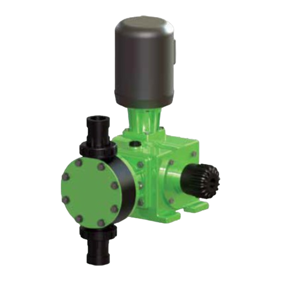
1. Introduction ® The GLM DM7 metering pump is positive displacement, mechanically operated reciprocating diaphragm pump. Each pump consists of a power end and a process end separated by a Teflon faced diaphragm. Individual pumps will vary in appearance due to various liquid ends and accessories; however, the basic principles of operation remain the same. -
Page 5: Reagent Head Assembly
This in turn causes the pushrod and diaphragm to travel over a longer distance. Refer to Section 6.2 for further information. For automatic flow rate control, users can consider the Pulsafeeder MPC speed based control system, please contact your local Pulsafeeder dealer or representative for more information. -
Page 6: Equipment Inspection
After twelve months of storage, Pulsafeeder’s warranty cannot cover items that are subject to deterioration with age, such as seals, gaskets, and diaphragms. If the pump has been in storage longer than 12 months it is recommended that these items be inspected and replaced as necessary prior to startup. -
Page 7: Piping System
Piping System 1. All systems should include a pressure relief valve on the discharge side, to protect piping and process equipment, including the pump, from excess process pressures. An external relief valve is required! There should be no devices capable of restricting flow (such as a valve) located between the pump and the relief device. - Page 8 In some cases, the proper line size may exceed the suction connection size on the pump. Consult your local Pulsafeeder Representative for assistance and further information on proper suction system design.
-
Page 9: Discharge Pressure Requirements
Discharge Pressure Requirements ® All GLM DM7 metering pumps are designed for continuous service at the rated discharge pressure. If system suction pressure exceeds discharge pressure (a condition sometimes described as “pumping downhill”), flow would be generated (siphoning) in addition to that caused by the pump. This results in a reduction in accuracy and loss of control over the metering process. -
Page 10: Equipment Startup
6. Equipment Startup Fastener Inspection All pump fasteners should be checked prior to pump operation, and occasionally during use. This would include reagent head mounting bolts, motor mounting bolts, and the hardware that secures the pump to its foundation. Most hardware can be checked simply to ensure it is not loose (proposal once a month when using process). -
Page 11: Oil Fill And Maintenance
® the GLM DM7 pump to specified levels are: Pump Capacity Gearbox, Model DM7 GLM Gear Oil 2,500 ml (2.6 Qt) Pulsafeeder Part No. Description Container Size GL980002-000 GLM Gear Oil 6.3.2 Gearbox Oil Fill Fill the gearbox with oil by removing the threaded oil fill cap on the top of the pump. Fill with the proper oil (GLM Gear Oil) to the upper edge of the sight glass on the side of the pump. -
Page 12: Priming The Reagent Head
6.3.3 Oil Changes The recommended oil change intervals are dependent upon the operating environment and level of pump usage, classified as follows: Normal service: Clean/dry atmosphere, an ambient operating temperature of 0 C to 40 F to 104 F) and up to 2,000 annual operating hours. Severe Service: Humid atmosphere, an ambient operating temperature below 0 C (32 F) or... - Page 13 6. Start the pump at the zero stroke length setting and slowly increase the setting to 100 to prime the pump. If this does not work, it will be necessary to fill the suction line. 7. Filling of the suction line will necessitate the use of a foot valve or similar device at the end of the suction line so that liquid can be maintained above the reservoir level.
-
Page 14: Calibration
Calibration Figure 7, sample flow calibration curve All metering pumps must be calibrated to accurately specify stroke length settings for required flow rates. A typical calibration chart is shown above. Although output is linear with respect to stroke length setting, an increase in discharge pressure decreases output uniformly, describing a series of parallel lines, one for each pressure (only two are shown). -
Page 15: Maintenance
7. Maintenance EFORE PERFORMING ANY MAINTENANCE REQUIRING REAGENT HEAD OR VALVE WET END DISASSEMBLY BE SURE TO RELIEVE PRESSURE FROM THE PIPING SYSTEM AND WHERE HAZARDOUS PROCESS MATERIALS ARE INVOLVED RENDER THE PUMP SAFE TO PERSONNEL AND THE ENVIRONMENT BY CLEANING AND CHEMICALLY NEUTRALIZING AS APPROPRIATE EAR PROTECTIVE CLOTHING AND EQUIPMENT AS APPROPRIATE Accurate records from the early stages of pump operation will indicate the type and levels of required maintenance. - Page 16 Figure 8, wet end components ® DM7 diaphragms do not have a specific cycle life; however, the accumulation of foreign material or debris sufficient to deform the diaphragm can eventually cause failure. Failure can also occur as a result of system over pressure or chemical attack. Periodic diaphragm inspection and replacement are recommended.
-
Page 17: Diaphragm Removal & Reinstallation
Diaphragm Removal & Reinstallation 1. Adjust the stroke setting to 0% and disconnect the power source to the drive motor. 2. Relieve all pressure from the piping system. Take all precautions described under the WARNINGS on page 14, Section 7 to prevent environmental damage and exposure of personnel to hazardous materials. - Page 18 6. Remove all but one top reagent head bolt. Product will leak out between the pump head adaptor and reagent head as the bolts are loosened. 7. Remove the final bolt and rinse or clean the reagent head with an appropriate material. 8.
-
Page 19: Diaphragm Shaft Seal
12. Thread the diaphragm (clockwise) fully onto the shaft. When reinstalling a used diaphragm it is not necessary to maintain the previous orientation relative to the reagent head or pump head hole pattern. 13. Remove the screwdriver from the oil fill hole and replace the cap. 14. -
Page 20: Check Valves
Check Valves Most fluid metering problems are related to check valves. Problems usually stem from solids accumulation between valve and seat, corrosion of seating surfaces, erosion, or physical damage due to wear or the presence of foreign objects. The valve incorporates a ball, guide, and seat. Flow in the unchecked direction lifts the ball off the seat, allowing liquid to pass through the guide. -
Page 21: Check Valve Removal & Reinstallation, Plastic Union-Nut Type
7.4 Check Valve Removal & Reinstallation, Plastic Union-Nut type 1. Disconnect the power source to the drive motor. 2. Relieve all pressure from the piping system, and take all precautions necessary to prevent contamination to the environment and personnel exposure to hazardous materials. -
Page 22: Check Valve Removal And Reinstallation, Metal Tie-Bar Type
Check Valve Removal and Reinstallation, Metal Tie-Bar type 1. Disconnect the power source to the drive motor. 2. Relieve all pressure from the piping system. 3. Take all precautions necessary to prevent contamination to the environment and personnel exposure to hazardous materials. 4. - Page 23 Figure 14, Check valves, metal construction...
-
Page 24: Motor Removal & Reinstallation
Motor Removal & Reinstallation 1. Disconnect the power source to the drive motor. 2. Disconnect the motor wiring from the motor. 3. Remove the four bolts retaining the motor to the motor adaptor. Lift the motor upwards away from the pump. 4. -
Page 25: Replacement Parts
Each KOPkit is vacuum-packed for extended storage. ® All GLM pumps have the KOPkit number identified on the pump nameplate and Pulsafeeder order documents. KOPkits can also be selected from the technical data sheet shipped with ® the pump or by a Pulsafeeder representative. A list of the GLM KOPkit numbers can also be found on the next page. -
Page 26: Kopkit Numbers By Model
KOPkit numbers by model: Pump Model Wetted Material Connection Type KOPkit number Polypropylene NPT / ISO / FLG KD7P KD7A NOTES: (1) DM1 through 6 models are covered in a separate publication (2) Polypropylene KOPkits are identical as only balls and insert o-rings are supplied 9. -
Page 27: Troubleshooting
10. Troubleshooting DIFFICULTY PROBABLE CAUSE REMEDY Faulty power source Check power source Blown fuse, circuit breaker overload Replace - eliminate Pump does not start Broken wire Locate and repair Wired improperly Check diagram Process piping blockage Open valves, clear other obstructions Check power source. - Page 28 DIFFICULTY PROBABLE CAUSE REMEDY Leak in suction line Locate and correct Product cavitating Increase suction pressure Entrained air or gas in product Consult factory for suggested venting Motor speed erratic Check voltage and frequency Delivery erratic Fouled check valves Clean, replace if necessary Increase discharge pressure to obtain a Inadequate backpressure minimum pressure difference of 5 psi from...
-
Page 29: Piping Accessories
11. Piping Accessories Pressure Relief Valves Pressure relief valves are designed to protect chemical feed systems from damage that may be caused by defective equipment or a blockage in the discharge line. These valves function to limit the pressure downstream of the pump. Field adjust the pressure relief valve to operate when the discharge pressure exceeds operating pressure by 10-15%. -
Page 30: Dimensional Drawing
12. D i m e ns i o na l Draw ings... -
Page 32: Parts Diagrams And Parts Lists
13. Parts Diagrams and Parts Lists... - Page 33 ITEM DESCRIPTION PART NUMBER ITEM DESCRIPTION PART NUMBER Flange Adaptor (P) NP300248-PPL Motor Adapor Plate 100 IEC NP490034-ALU Flange Adaptor (F) NP300248-KYN Motor Adapor Plate NEMA 56c,145TC NP490033-ALU Flange Adaptor(A) GL360008-STL Motor Bolt IEC 100 W770534-188 Flange Adaptor BOLT (A) NP993931-188 Motor Bolt NEMA 56c,145TC W770424-188...
- Page 34 Leak Detection Standard KOPKIT List KOPKIT P/N: KD7PL KD7PL KOPKIT BOM List Item# Part Number Part Description Q’ty NP140101-316 PLATE, FRONT REFLECT NP140102-STL PLATE, REAR REFLECT NP170065-TFE DIAPHRAGM NP180046-PPL SPACER NP530227-000 Switch OBL Leak Detection NP560030-316 PRESSURE GAUGE(0-200PSI) DUAL SCALE NP990543-188 BOLT M10-1.5 X 130 SS NP990544-188...
- Page 36 Introduction of QR code Thanks for purchasing Pulsafeeder metering pump, you can scan the QR code on the name plate to check the security information, KOPkits information, Manual and connection information. Using description is below: 1 , Scan the QR code on the name plate 2 ,...
Need help?
Do you have a question about the PULSA GLM7 and is the answer not in the manual?
Questions and answers