
Related Manuals for Pulsafeeder PULSAR Shadow Series


Summary of Contents for Pulsafeeder PULSAR Shadow Series
- Page 1 Installation, Operation & Maintenance Manual ® PULSAR Shadow MECHANICAL DIAPHRAGM Bulletin: IOM-PSRM-1501 REV B METERING PUMP...
- Page 2 Solutions may include purchase of replacement parts or returning the unit to the factory for inspection and repair. All returns require a Return Authorization number to be issued by Pulsafeeder. Parts purchased to correct a warranty issue may be credited, after an examination of original parts by Pulsafeeder. Warranty parts returned as defective which test good will be sent back freight collect.
-
Page 3: Table Of Contents
Table of Contents 1. I ............................. 1 NTRODUCTION Overall Operation ........................1 Component Layout ........................2 Standard Reagent Head Assembly ..................3 Leak Detection Assembly ....................... 4 Control Assembly ........................5 Gear Ratio Assembly ......................6 2. E ........................6 QUIPMENT NSPECTION 3. - Page 4 PULSAR Shadow® KOPkit Program ..................27 Ordering KOPkits or Parts ...................... 27 9. T ........................28 ROUBLESHOOTING HART 10. APPENDIX I P ....................30 IPING ALCULATIONS 10.1 Suction Head Requirements ....................30 10.2 System Backpressure ......................31 11. APPENDIX II ....................
- Page 5 Conventions The following Conventions are used in this document. WARNING DEFINES A CONDITION THAT COULD CAUSE DAMAGE TO BOTH THE EQUIPMENT AND THE PERSONNEL OPERATING IT AY CLOSE ATTENTION TO ANY WARNING NOTES ARE GENERAL INFORMATION MEANT TO MAKE OPERATING THE EQUIPMENT EASIER.
-
Page 6: Introduction
1. Introduction ® PULSAR Shadow metering pumps are positive displacement reciprocating pumps. They combine the high efficiency of the plunger pump with diaphragm sealing to prevent product leakage. Each pump consists of a power end and a process end separated by a mechanically operated diaphragm. -
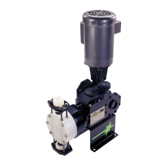
Page 7: Component Layout
1.2 Component Layout Figure 2 A typical model with manual external stroke adjustment is shown. -
Page 8: Standard Reagent Head Assembly
1.3 Standard Reagent Head Assembly Figure 3 The typical reagent head assembly consists of reagent head, diaphragm, and suction and discharge check valves. This assembly is the only part of the pump to contact the process liquid; consequently, maintenance is critical to pump performance. For most pump configurations, suction and discharge check valve components are identical. -
Page 9: Leak Detection Assembly
This pressure will activate the pressure switch. It is recommended that the pressure switch be integrated into a control system that will shut the pump off if a leak is detected. The pressure switch may be wired directly to a Pulsafeeder DLC or DLCM controller if the pump is so equipped. -
Page 10: Control Assembly
1.5 Control Assembly Figure 5 PULSAR Shadow® pumps incorporate a lost motion style of stroke length adjustment to limit diaphragm travel during the suction portion of each stroke. The stroke length setting is indicated by a (0 - 100) scale located on the top of the unit. Stroke length is changed by depressing and turning the hand knob. -
Page 11: Gear Ratio Assembly
1.6 Gear Ratio Assembly Figure 6 ® PULSAR Shadow pumps are driven by a standard C-face electric motor mounted on the motor adaptor input flange. The motor drives a set of worm gears, which convert rotational speed into torque. They, in turn, power the eccentric shaft assembly that converts rotary motion into reciprocating motion. The drive motor can be wired to rotate in either direction. -
Page 12: Storage Instructions
After twelve months of storage, Pulsafeeder’s warranty cannot cover items that are subject to deterioration with age such as seals and gaskets. If the pump has been in storage longer than 12 months it is recommended that such items be inspected and replaced as necessary prior to startup. -
Page 13: Installation
4. Installation 4.1 Location When selecting an installation site or designing a skid package, consideration should be given to access for routine maintenance. PULSAR Shadow® pumps are designed to operate indoors and outdoors, but it is desirable to provide a hood or covering for outdoor service. External heating is required if ambient temperatures below 0O C (32O F) are anticipated. -
Page 14: Suction Pressure Requirements
An inlet strainer, if the product is not a slurry. Pump check valves are susceptible to dirt and other solid contaminants unless designed for that service, and any accumulation can cause malfunction. The strainer should be located between the suction shutoff valve and the pump suction valve. -
Page 15: Automatic Control
4.5 Automatic Control Pumps equipped with the DLC, DLCM, or ECA electronic stroke length controllers are provided with separate instructions. Refer to the latest Installation, Operation and Maintenance Manual specific to your controller. Follow all safety and operational information contained in those documents. Perform and verify all controller installation procedures prior to pump startup. -
Page 16: Leak Detection Assembly
4.6 Leak Detection Assembly Figure 10 If the diaphragm leak detection system was specified with an optional pressure switch, install electrical wiring and conduit in accordance with local electrical codes. The switch is rated as follows: The switch is rated as follows: 30 VDC or 125 VAC 1 Ampere Resistive. -
Page 17: Electrical
If the motor is to be utilized with a Pulsafeeder controller, such as the DLC or DLCM, consult the appropriate Pulsafeeder IOM for further motor wiring instructions. -
Page 18: Oil Capacities
5.1 Oil Capacities Pulsalube 9M lubricating oil is available in 950 ml (1 quart) containers. Pulsalube 8G gear oil is available in 200 ml (.21 quarts) or 950 ml (1 quart) containers. It is recommended that adequate supplies of both PULSAlube oils be on hand for periodic changes and emergency requirements. -
Page 19: Oil Changes
5.4 Oil Changes The recommended oil change intervals are dependent upon the operating environment and level of pump usage, classified as follows: Normal service: Clean/dry atmosphere, an ambient operating temperature of 00˚C to 400˚C (320˚F to 1040˚F) and up to 2,000 annual operating hours. Severe Service: Humid atmosphere, an ambient operating temperature below 00˚C (320˚F) or above 400˚C (1040˚F), and over 2,000 annual operating hours. -
Page 20: Startup
6. Startup 6.1 Output Adjustment Figure 13 ® PULSAR Shadow pumps have a handwheel for manual stroke length adjustment. Mounted atop the eccentric box, the handwheel can be adjusted at any point from (0 to 100%) stroke setting by pressing down and then rotating as required. Stroke length is locked during operation to prevent drift: pressing the handwheel down temporarily disengages the lock for adjustment;... -
Page 21: Calibration
discharge valve assembly and fill the reagent head as described in Step (3) above. The pump will now self-prime when started up per step (4) above. 6.3 Calibration Figure 14 All metering pumps must be calibrated in order to accurately specify stroke length settings for required flow rates. -
Page 22: Leak Detection
6.4 Leak Detection Figure 15 Follow the same priming procedure for a standard reagent for pumps equipped with the diaphragm leak detection system. If the optional pressure switch has been supplied, apply power to the alarm circuit. It is recommended that this switch be integrated into the pump control system. If a failure of the diaphragm is detected, the pump should be shut down until a diagnosis of the fault can be made. -
Page 23: Maintenance
7. Maintenance EFORE PERFORMING ANY MAINTENANCE REQUIRING REAGENT HEAD OR VALVE DISASSEMBLY BE SURE TO RELIEVE PRESSURE FROM THE PIPING SYSTEM AND WHERE HAZARDOUS PROCESS MATERIALS ARE INVOLVED RENDER THE PUMP SAFE TO PERSONNEL AND THE ENVIRONMENT BY CLEANING AND CHEMICALLY NEUTRALIZING AS APPROPRIATE EAR PROTECTIVE CLOTHING AND EQUIPMENT AS REQUIRED Accurate records from the early stages of pump operation will indicate the type and... -
Page 24: Leak Detection
PULSAR Shadow® diaphragms do not have a specific cycle life; however, the accumulation of foreign material or debris sufficient to deform the diaphragm can eventually cause failure. Failure can also occur as a result of system over pressure or chemical attack. Periodic diaphragm inspection and replacement are recommended. 1. -
Page 25: Check Valves
7.2 Check Valves 7.2.1 General Description Most fluid metering problems are related to check valves. Problems usually stem from solids accumulation between valve and seat, corrosion of seating surfaces, erosion, or physical damage due to wear or the presence of foreign objects. The valve incorporates a ball, guide, and seat. -
Page 26: Oil Seals - General Description
10. Reassemble both valves using new parts as required. Sealing “O”-rings should generally be replaced. 11. Reinstall both valve assemblies, taking care to ensure that they are correctly oriented with balls above seats. 12. Tighten the tiebar bolts evenly, making sure the valve assemblies are assembled squarely. -
Page 27: Removal And Replacement
7.4 Removal and Replacement To replace the pump shaft seal: Following the instructions in the previous sections, remove the reagent head assembly. Then remove the diaphragm. Remove the pump shaft by unscrewing counter-clockwise. Take care not to allow any shims to drop into the eccentric box when removing the shaft. A thread-locking compound is used between the pump shaft and the crosshead assembly. - Page 28 To replace the gearbox oil seal: First drain the gearbox per the lubrication instructions. Remove the four gearbox bolts, and withdraw the gearbox from the eccentric box, sliding it off the eccentric shaft. Remove the seal. Lubricate the replacement with Pulsalube 8G gear oil and install by pressing into position.
- Page 29 To replace the eccentric box seal: First remove the gearbox per step 3 above. Remove the four bolts, which retain the eccentric side cap to the eccentric box. Remove the eccentric side cap and withdraw the eccentric shaft. Remove the seal. Lubricate the replacement with Pulsalube 8G gear oil and install by pressing it into position.
-
Page 30: Cover Assembly
7.5 Cover Assembly 7.5.1 Removal and Reinstallation Figure 21 The hand knob linkage employs a slip type coupling which can be reassembled in either of two rotational orientations 180 apart from one another: therefore, the original orientation must be retained for reassembly so that pump calibration is retained. 7.5.2 Removal 1. -
Page 31: Reinstallation
7.5.3 Reinstallation 1. Rotate the stroke cam screw clockwise until the slider cam is in a full upward position. 2. Verify that the cover dial indicates the zero stroke setting. 3. Using care not to disturb the adjustment shaft, install the cover assembly, engaging the drive coupling. -
Page 32: Replacement Parts
® model. Each KOPkit is vacuum-packed for extended storage. All PULSAR Shadow pumps have the KOPkit number identified on the pump nameplate and Pulsafeeder order documents. KOPkits can also be selected from the technical data sheet shipped with the pump or with the assistance of a Pulsafeeder representative. -
Page 33: Troubleshooting Chart
9. Troubleshooting Chart Difficulty Probable Cause Remedy Coupling disconnected Connect coupling Faulty power source Check power source Pump does not Blown fuse, and circuit breaker Replace - eliminate overload start Broken wire Locate and repair Wired improperly Check diagram Pipe line blockage Open valves Motor not running Check power source. - Page 34 Increase size of piping - install pulsation Pipe size too small dampener Pipe runs too long Install pulsation dampener in line Piping noisy Replace with air or inert gas. If a pulsation Surge chambers flooded dampener is installed, replace diaphragm and recharge No surge chambers used Install pulsation dampener...
-
Page 35: Appendix I Piping Calculations
10. APPENDIX I Piping Calculations 10.1 Suction Head Requirements All reciprocating metering pumps require a net positive suction head (NPSHR). The NPSHR for PULSAR Shadow® pumps is 5 psi (0.35 bar). The NPSHR is defined as the pressure required above the absolute vapor pressure of the process fluid at the pumping temperature. -
Page 36: System Backpressure
10.2 System Backpressure The system backpressure must exceed the suction pressure by at least 5 psi (0.35 bar) in order to prevent flowthrough, however it must not exceed the rated discharge pressure of the pump. Flowthrough can be defined as the process liquid flowing from a higher pressure to a lower pressure (downhill pumping), which results in a flow output greater than the pumps calibrated capacity, failure and undesired flow at pump shutdown. -
Page 37: Appendix Ii Oil Specifications
11. APPENDIX II Oil Specifications PULSAlube #8G AGMA Number 7 EP ISO Viscosity Grade API Gravity (ASTM D 287) 34.1 Viscosity (ASTM D 2161) SSU @ 100˚F 2241 Viscosity (ASTM D 2161) SSU @ 210˚F Viscosity Index (ASTM D 2270) Pour Point (ASTM D 97) ˚F8 -40(-40) Flash Point, COC (ASTM D 92) ˚F8... -
Page 38: Bolt Torque Tables
12. APPENDIX III Bolt Torque Tables PULSAR – Liquid End Bolt Torque Requirements Metal Construction Reagent Head Bolts Tie Bars Head Part Head Torque Torque # Bolts and #Bolts and Number Size Size Size ft-lb ft-lb NP160001 (6) M10*1.5 (4) M8*1.25 NP160002 (6) M12*1.75 (4) M8*1.25... -
Page 39: Appendixv Pulsafeeder Accessories
13. Appendix V Pulsafeeder Accessories 13.1 Pulsation Dampeners The PULSAtrol pulsation dampener is a pneumatically charged diaphragm-type chamber that intermittently stores energy. Used on the inlet, it can improve NPSHa (Net Positive Suction Head available) characteristics of the suction piping system. On the discharge line it will reduce peak pressures and pulsating flow variations. - Page 40 Discharge Setup The pulsation dampener may be precharged with air or nitrogen. When properly precharged the diaphragm is positioned against the bottom liquid chamber. It is therefore necessary to drain all liquid below the diaphragm and vent to atmospheric pressure when precharging. Use the precharge pressure as determined from the pulsation dampener selection and sizing procedure (Catalog No.
-
Page 41: Pulsation Dampener Removal
13.3 Pulsation Dampener Removal When removing or disassembling a pulsation dampener, drain all piping and remove all air and process pressure. Assume that the diaphragm is broken and the chamber is flooded under pressure since the pressure gauge could be damaged. Separate chambers with caution in a direction away from the body. - Page 46 ® PULSAR Shadow MECHANICAL DIAPHRAGM METERING PUMP Bulletin: IOM-PSRM-1501 Pulsafeeder, Inc. A unit of IDEX Corporation 2883 Brighton Henrietta Town Line Road Rochester NY 14623 +1 (585) 292-8000 www.pulsa.com pulsa@idexcorp.com...
Need help?
Do you have a question about the PULSAR Shadow Series and is the answer not in the manual?
Questions and answers