Table of Contents
Advertisement
Quick Links
DYNAMIC STRAIN AMPLIFIER CARD for EDX SERIES
This Instruction Manual may not be copied or reproduced, in whole or part, without consent of KYOWA.
Copyright © KYOWA ELECTRONIC INSTRUMENTS CO., LTD. All rights reserved.
The contents of the Instruction Manual are subjected to change without prior notice.
I N S T R U C T I O N M A N U A L
DPM-42B/DPM-42B-I
DPM-42B-F/DPM-42B-I-F
Thank you for purchasing KYOWA's product
DPM-42B/DPM-42B-I/DPM-42B-F/DPM-42B-I-F Dynamic Strain Amplifier
Card for EDX series.
Read this Instruction Manual carefully in order to make full use of the high
performance capabilities of the product.
Do not use the product in methods other than described in this Manual.
IM-A-897E January 2024
Advertisement
Table of Contents

Related Manuals for KYOWA DPM-42B


Summary of Contents for KYOWA DPM-42B
- Page 1 Do not use the product in methods other than described in this Manual. This Instruction Manual may not be copied or reproduced, in whole or part, without consent of KYOWA. Copyright © KYOWA ELECTRONIC INSTRUMENTS CO., LTD. All rights reserved.
-
Page 2: Table Of Contents
INFORMATIONAL NOTES ..................3 1. OUTLINE OF THE PRODUCT ................... 4 1-1 OUTLINE OF THE DPM CARDS ................4 1-2 OUTLINE OF THE DPM-42B-I/42B-I-F ..............4 1-3 OUTLINE OF THE DPM-42B-F/42B-I-F ..............4 1-4 PRECAUTIONS FOR USING DPM CARDS ..............5 1-5 PRECAUTIONS FOR USING DPM-42B-F/42B-I-F ............ -
Page 3: Standard Accessories
This Manual describes the DPM-42B/DPM-42B-I/DPM-42B-F/DPM-42B-I-F Dynamic Strain Amplifier Card (hereinafter referred to as the DPM cards) for the EDX series. Differences in specifications among the above cards are described in the following table. Model Anti-inverter-noise function Anti-aliasing filter function DPM-42B DPM-42B-I ✔... -
Page 4: Prior To Use
For safe use of the DPM card, do not forget to read the "SAFETY PRECAUTIONS" prior to use. KYOWA ELECTRONIC INSTRUMENTS CO., LTD. assumes no liability for any damage resulting from the user’s failure to comply with the safety precautions. -
Page 5: Limited Life Parts And Preventive Maintenance
To operate the DPM card normally, finding a sign of the DPM card failure early by daily/periodic inspections and taking the corrective action are required. For inspection, contact KYOWA or our representatives. * Limited life parts used with the DPM card are aluminum electrolytic capacitors and relays. -
Page 6: Outline Of The Product
The DPM-42B-I/42B-I-F can measure data precisely by reducing inverter noise. 1-3 OUTLINE OF THE DPM-42B-F/42B-I-F The DPM-42B-F/-42B-I-F card is a DPM-42B (-I) conditioner card provided with anti-aliasing filter function. Using the anti-aliasing filter function prevents aliasing caused by sampling. The anti-aliasing filter of the DPM card is composed of eighth order butterworth filter and attenuation obtained by entering 1/2 of sampling frequency is -48 ±5 dB. -
Page 7: Precautions For Using Dpm Cards
After the power ON, the DPM card requires a certain time to become stable. To have the stable measurement, preheat for more than 30 minutes. 1-5 PRECAUTIONS FOR USING DPM-42B-F/42B-I-F Cutoff frequency of the anti-aliasing filter is set to 1/4 of the sampling frequency. Set the sampling frequency to at least more than 4 times the predicted input frequency. -
Page 8: Controls And Indicators
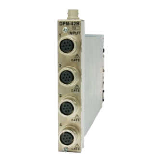
1-6 CONTROLS AND INDICATORS ⑤ ① ② ③ ④ Input connector 1 Input connector of the 1st channel. ① Input connector 2 Input connector of the 2nd channel. ② Input connector 3 Input connector of the 3rd channel. ③ Input connector 4 Input connector of the 4th channel. -
Page 9: Pin Assignment And Connection Of Input Connector
1-7 PIN ASSIGNMENT AND CONNECTION OF INPUT CONNECTOR [Pin assignment] ① Input connector DPM-42B Pin assignment of input connectors (TAJIMI ELECTRONICS CO., LTD.) Pin No. Signal Name + Bridge Excitation - Input - Bridge Excitation + Input FG (GND) ID signal + FG (GND) Channel No. - Page 10 For how to connect the DPM card to a bridge box, see "Measurement Memo: How to Assemble a Bridge Gage Bridge" in KYOWA's union catalog or bridge box instruction manual. When one end of the strain gage transducer is equipped with no plug, there are 2 ways for connecting the strain gage transducer to the DPM card.
- Page 11 (2) When connecting a monitor output cable to a monitor output connector Connect the optional monitor output cable [H-10296]. How to connect the monitor output cable is described in the following figure. The output connector is BNC connector. A E R05-PB5M(Cable side: TAJIMI made) B...
-
Page 12: Installation Of Dpm Cards
EDX series hardware. Contact our representative for updating the EDX series hardware. DPM cards are installed in slot No. 1 Slot No. Card Type and 2. DPM-42B DPM-42B *** *** NOTE When installing or removing the DPM card, do not touch any component parts of the DPM card. -
Page 13: How To Set The Dpm Cards
9) Oscillator ↓ Initial Screen <Oscillator setting> Initial Screen When the DPM card is correctly installed in the EDX-2000A/B, "DPM-42B" appears on the initial screen. (The following screen shows that ‘4' DPM cards are installed.) First slot: DPM-42B Second slot:... - Page 14 Environment Select item 5) <Environment> from the main menu of the initial screen to display the right screen. Put the cursor to menu item 9) <Oscillator> and press the ENTER key. Oscillator An "Oscillator" setting window appears as shown at the right.
-
Page 15: Setting Channels
30Hz SHUNT 10k μm/m 10Hz 20k μm/m AUTO* 50k μm/m ↓ *Displayed on the DPM-42B-F/42B-I-F. Initial Screen (Note) Selectable range varies with Mode. ↓ 1) Measurement <Channel settings> Initial Screen Put the cursor to menu item 2) <Condition> and press the ENTER key. - Page 16 Conditions Screen Select item 2) <Condition> from the main menu of the initial screen to display the right screen. Put the cursor to menu item 1) <Channel Cond> and press the ENTER key. MEMO If no conditioner card is installed, channel column and items that are not available for setting are indicated with "*."...
- Page 17 Range Select item 3) <Range> from the <Channel Cond> menu. An "Range" setting window appears as shown at the right. BV (2.0 V): 200μm/m, 500μm/m, 1kμm/m, 2kμm/m, 5kμm/m, 10kμm/m, 20kμm/m, or OFF BV (0.5 V): 1kμm/m, 2kμm/m, 5kμm/m, 10kμm/m, 20kμm/m, 50kμm/m, or OFF It is required to select an appropriate "Range"...
- Page 18 Compatible sampling frequency range of the anti-aliasing filter is 100 Hz or more. Although the card is DPM-42B-F/42B-I-F, if "AUTO" is not displayed on the "Low Pass Filter" setting window, check whether or not the sampling frequency is set to less than 100 Hz.
- Page 19 Balance ON/OFF Select item 5) <BAL ON/OFF> from the <Channel Cond> menu. An "Balance ON/OFF" setting window appears as shown at the right. Put the cursor to either "ON" or "OFF" and press the ENTER key. Only channels that are set to "ON"...
- Page 20 NOTE When balance is executed to the DPM card, not only initial balance is adjusted when sensors are connected or changed but also offset value is calculated when standard equivalent strain (CAL) is entered. When the following conditions are changed, re-execute the balance once again. ...
- Page 21 When SHUNT is selected Input fixed resistance between [+ Bridge excitation] and [- Input] of the strain gage bridge and add a certain value to the current output and display the obtained value. The output value is determined by the bridge resistance of the strain gage bridge irrespective of the CAL range.
- Page 22 Measurement After all the settings are complete, select item 0) <End> from the <Channel Cond> menu to return to the initial screen as shown at the right. Select item 1) <Measurement> from the main menu to start the measurement with the determined channel conditions.
-
Page 23: Setting Internal Sensitivity Compensation
2-1-3 Setting Internal Sensitivity Compensation Internal sensitivity compensation is a function used in the following case. When setting the oscillator to the "external oscillator." When compensating sensitivity When the input cable is long. When connecting a sensor for the first time. ... - Page 24 Conditions Screen Select item 2) <Condition> from the main menu of the initial screen to display the right screen. Put the cursor to menu item 6) <Comp IntSense> and press the ENTER key. Comp IntSense Select item 6) <Comp IntSense> of the Conditions Screen to display the right screen.
- Page 25 If there are channels that are set to "ON" for "Comp Target", menu items 2) <Compensate> and 3) <Initialize> are added to the menu. Put the cursor to menu item 2) <Compensate> and press the ENTER key. Compensate An "Compensate" window appears as shown at the right.
- Page 26 Sensitivity of channels, subjected to internal sensitivity compensation, are compensated. To initialize the internal sensitivity compensation, put the cursor to item 3) <Initialize> and press the ENTER key. Initialize An "Initialize" window appears as shown at the right. Execute initialization → ENTER key Stop initialization →...
-
Page 27: By Using The Edx-100A
2-2 BY USING THE EDX-100A With the EDX-100A, settings are executed by using the EDX-100A or Dynamic Data Acquisition Software DCS-100A. 2-2-1 Environment Set items in the following procedures. Initial Screen ↓ Environment ↓ Oscillator ↓ Initial Screen <Settings> Initial Screen - 25 -... - Page 28 Environment Open the Set Environment window as described below: Click the File - Environment. Click the Envr. icon from the toolbar. Envr. icon Click The following window appears. Click the Configuration tab on the Set Environment window. Click - 26 -...
- Page 29 Click Click the Read the configuration of the connecting devices... button. The EDX-100A is searched online for loading the hardware configuration. Before pressing, make sure the control interface and ID No. of the EDX-100A are correct. The above message appears. Click the Yes button. Click the OK button.
- Page 30 Oscillator Set an oscillator for carrier wave that is used for the DPM card. The carrier wave frequency is approximately 12 kHz. When the DPM card is installed, do not forget to confirm the setting of the oscillator. There are 2 types of oscillators, internal and external.
-
Page 31: Setting Channels
30 Hz SHUNT 10k μm/m 10 Hz 20k μm/m AUTO* 50k μm/m ↓ *Displayed on the DPM-42B-F/42B-I-F. Initial Screen (Note) Selectable range varies with Mode. ↓ Measurement <Channel settings> Initial Screen Open the Set CH Condition window as described below: ... - Page 32 Set CH Condition window The following window appears. Measurement ON/OFF Put a check mark to the check box next to the target channel. Mode Set the "Mode". Select BV (2.0 V) or BV (0.5 V) from the list box. Range Set the "Range".
- Page 33 Using a strain gage ① Estimate the magnitude of the strain to be measured. Estimate the magnitude of the strain by considering the material or structure of the target to be measured. ② Set the "Range" to a larger than and most approximate value to the magnitude of the estimated strain. ...
- Page 34 Compatible sampling frequency range of the anti-aliasing filter is 100 Hz or more. Although the card is DPM-42B-F/42B-I-F, if "AUTO" is not displayed on the "Low Pass Filter" setting window, check whether or not the sampling frequency is set to less than 100 Hz.
- Page 35 Balance ON/OFF Put a check mark to the check box next to the target channel. Only channels with a check mark are allowed for executing initial balance during measurements. NOTE During recording measured data, executing balance is not available. To execute balance, click the BAL button on the Meas Operation Panel (see the left figure). After a while, it automatically ends balancing and the balanced results are displayed on the window.
- Page 36 Comp IntSense ON/OFF Put a check mark to the check box next to the target channel. Before executing the internal sensitivity compensation (see 2-2-3 Setting Internal Sensitivity Compensation ), put a check mark, CAL Range Set the output value of the CAL. Select "100%", "50%", or "SHUNT"...
- Page 37 To execute CAL, click the CAL button on the Meas Operation Panel (see the left figure). The following operations are repeated every time the CAL button is pressed. Monitoring CAL: ON (+) (CAL OFF) CAL: ON (-) CAL button MEMO ...
-
Page 38: Setting Internal Sensitivity Compensation
2-2-3 Setting Internal Sensitivity Compensation Internal sensitivity compensation is a function used in the following case. When setting the oscillator to the "external oscillator." When compensating sensitivity When the input cable is long. When connecting a sensor for the first time. ... - Page 39 Set CH Condition window The following window appears. Only channels with a check mark on the Measurement ON/OFF column are allowed for executing internal sensitivity compensation. Click the Comp IntSense... button. Click Comp IntSense... button Click the Comp IntSense... button. The following window appears. To execute the internal sensitivity compensation, click the Yes button.
- Page 40 For channels indicated with "NG", re-check sensors and connection cable of the relevant channels, remove the cause and execute balance once again. Confirm compensation results of all the channels are all "OK". Sensitivity of channels, subjected to internal sensitivity compensation, are compensated. Initialize Sensitivity of channels, subjected to internal sensitivity compensation, are compensated.
-
Page 41: By Using The Edx-3000A
2-3 BY USING THE EDX-3000A With the EDX-3000A, settings are executed by using the EDX-3000A or Dynamic Data Acquisition Software DCS-100A. 2-3-1 By Using the EDX-3000A 2-3-1-1 Environment With the EDX-3000A, set items in the following procedures. Initial Screen ↓ Environment ↓... - Page 42 Environment Open the Set Environment window as described below: Click the File - Environment. Click the Envr. icon from the toolbar. Envr. icon Click The following window appears. Click the Configuration tab on the Set Environment window. Click - 40 -...
- Page 43 When the EDX series is used as the synchronous The model appears. master, select the "Synchronous mater" and click the Read the configuration of the connecting devices... button. The model appears on the Set Environment window. When the EDX series is used as the synchronous master, hardware configuration of slave units are also appear on the Set Environment window.
- Page 44 Oscillator Set an oscillator for carrier wave that is used for the DPM card. The carrier wave frequency is approximately 12 kHz. When the DPM card is installed, do not forget to confirm the setting of the oscillator. There are 2 types of oscillators, internal and external.
-
Page 45: Setting Channels
30 Hz SHUNT 10k μm/m 10 Hz 20k μm/m AUTO* 50k μm/m ↓ *Displayed on the DPM-42B-F/42B-I-F. Initial Screen (Note) Selectable range varies with Mode. ↓ Measurement <Channel settings> Initial Screen Click the CH Cond. icon from the toolbar. - Page 46 Set CH Condition window The following window appears. Measurement ON/OFF Put a check mark to the check box next to the target channel. Mode Set the "Mode" for each channel. Select BV (2.0 V) or BV (0.5 V) from the list box. Range Set the "Range".
- Page 47 Using a strain gage ① Estimate the magnitude of the strain to be measured. Estimate the magnitude of the strain by considering the material or structure of the target to be measured. ② Set the "Range" to a larger than and most approximate value to the magnitude of the estimated strain. ...
- Page 48 Compatible sampling frequency range of the anti-aliasing filter is 100 Hz or more. Although the card is DPM-42B-F/42B-I-F, if "AUTO" is not displayed on the "Low Pass Filter" setting window, check whether or not the sampling frequency is set to less than 100 Hz.
- Page 49 Balance ON/OFF Put a check mark to the check box next to the target channel. Only channels with a check mark are allowed for executing initial balance during measurements. NOTE During recording measured data, executing balance is not available. To execute balance, click the BAL button on the Meas Operation Panel (see the left figure). After a while, it automatically ends balancing and the balanced results are displayed on the window.
- Page 50 Comp IntSense ON/OFF Put a check mark to the check box next to the target channel. Before executing the internal sensitivity compensation (see 2-3-1-3 Setting Internal Sensitivity Compensation), put a check mark. CAL Range Set the output value of the CAL. Select "100%", "50%", or "SHUNT"...
- Page 51 To execute CAL, click the CAL button on the Meas Operation Panel (see the left figure). The following operations are repeated every time the CAL button is pressed. Monitoring CAL: ON (+) (CAL OFF) CAL button CAL: ON (-) MEMO ...
-
Page 52: Setting Internal Sensitivity Compensation
2-3-1-3 Setting Internal Sensitivity Compensation Internal sensitivity compensation is a function used in the following case. When setting the oscillator to the "external oscillator." When compensating sensitivity When the input cable is long. When connecting a sensor for the first time. ... - Page 53 Set CH Condition window The following window appears. Only channels with a check mark on the Measurement ON/OFF column are allowed for executing internal sensitivity compensation. Click the Comp IntSense... button. Click Comp IntSense... button Click the Comp IntSense... button. The following window appears. To execute the internal sensitivity compensation, click the Yes button.
- Page 54 For channels indicated with "NG", re-check sensors and connection cable of the relevant channels, remove the cause and execute balance once again. Confirm compensation results of all the channels are all "OK". On and after then, internal sensitivity compensation of the channels are active. Initialize Sensitivity of channels, subjected to internal sensitivity compensation, are compensated.
-
Page 55: By Using The Dcs-100A
2-3-2 By Using the DCS-100A 2-3-2-1 Environment With the Dynamic Data Acquisition Software DCS-100A, set items in the following procedures. Set Environment window of the EDX-3000A ↓ Initial Screen ↓ Environment ↓ Oscillator ↓ Initial Screen <Settings> Set Environment window of the EDX-3000A Click To control the EDX-3000A by using the Dynamic Data Acquisition Software DCS-100A, set the control mode to "Online". - Page 56 Environment Open the Set Environment window of the DCS-100A as described below: Click the File - Environment. Click the Envr. icon from the toolbar. Envr. icon Click The following window appears. Click the Configuration tab on the Set Environment window. Click - 54 -...
- Page 57 Click the Read the configuration of the connecting devices... button. The EDX-100A is searched online for loading the hardware configuration. Click The above message appears. Click the Yes button. The right message appears. Click the Yes button. The new hardware configuration will appear on the Connection Configuration window.
-
Page 58: Setting Internal Sensitivity Compensation
Oscillator Set an oscillator for carrier wave that is used for the DPM card. The carrier wave frequency is approximately 12 kHz. When the DPM card is installed, do not forget to confirm the setting of the oscillator. There are 2 types of oscillators, internal and external. -
Page 59: Setting Channels
2-3-2-2 Setting Channels For details, see 2-2-2 Setting Channels. 2-3-2-3 Setting Internal Sensitivity Compensation For details, see 2-2-3 Setting Internal Sensitivity Compensation. - 57 -... -
Page 60: By Using The Edx-200A
2-4 BY USING THE EDX-200A With the EDX-100A, settings are executed by using the Dynamic Data Acquisition Software DCS-100A. 2-4-1 Environment Set items in the following procedures. Initial Screen ↓ Environment ↓ Oscillator ↓ Initial Screen <Settings> Initial Screen - 58 -... - Page 61 Environment Open the Set Environment window as described below: Click the File - Environment. Click the Envr. icon from the toolbar. Envr. icon Click The following window appears. Click the Configuration tab on the Set Environment window. Click - 59 -...
- Page 62 Click the Check Connected Device... button. The EDX-200A is searched online for loading the hardware configuration. Before pressing, make sure the control interface and ID No. of the EDX-200A are correct. Click The right message appears. Click the Yes button. Click the OK button.
-
Page 63: Setting Internal Sensitivity Compensation
Oscillator Set an oscillator for carrier wave that is used for the DPM card. The carrier wave frequency is approximately 12 kHz. When the DPM card is installed, do not forget to confirm the setting of the oscillator. There are 2 types of oscillators, internal and external. -
Page 64: Setting Channels
2-4-2 Setting Channels For details, see 2-2-2 Setting Channels . 2-4-3 Setting Internal Sensitivity Compensation For details, see 2-2-3 Setting Internal Sensitivity Compensation . - 62 -... -
Page 65: Specifications
-3 ±1dB Attenuation: -12 ±1dB/oct. Signal-noise ratio 【DPM-42B/DPM-42B-F】 50dB or more (Range: 500 μm/m, Low pass filter: FLAT) 【DPM-42B-I/DPM-42B-I -F】 44dB or more (Range: 500 μm/m, Low pass filter: FLAT) Resolution 16 bits Monitor output Accuracy: ±5 V±0.5% (full scale in plus and minus directions) Nonlinearity: Within ±0.5%FS... -
Page 66: Outside Drawing
3.2 OUTSIDE DRAWING <DPM-42B> <DPM-42B-I> - 64 -... - Page 67 <DPM-42B-F> <DPM-42B-I-F> - 65 -...
-
Page 68: Optional Accessories
4. OPTIONAL ACCESSORIES Monitor Output Cable <H-10296> By connecting to a monitor BNC connector, this monitor output cable is capable of monitoring data for every CH. (Length: Approx. 2 m) For details, see " 1-7 PIN ASSIGNMENT AND CONNECTION OF INPUT CONNECTOR ." - 66 -...
Need help?
Do you have a question about the DPM-42B and is the answer not in the manual?
Questions and answers