Table of Contents
Advertisement
Quick Links
This product is a copyrighted work of KYOWA ELECTRONIC INSTRUMENTS CO., LTD. All rights
reserved.
Copying or reproduction of this product, whether in part or whole, is strictly prohibited without permission.
The contents of this Manual are subject to change without prior notice.
CHARGE AMPLIFIER CARD
CCA-40A/CCA-40A-F
I
NSTRUCTION MANUAL
Thank you for purchasing KYOWA's product, CCA-40A/CCA-40A-F Charge Amplifier
Card for EDX-2000A Memory Recorder/Analyzer.
Read this manual carefully to ensure the long life and reliability of the product.
The product should not be used in any manners other than as described in this Instruction
Manual.
IM-A-599B February 2023
for EDX-2000A
Advertisement
Table of Contents

Related Manuals for KYOWA CCA-40A


Summary of Contents for KYOWA CCA-40A
- Page 1 The product should not be used in any manners other than as described in this Instruction Manual. This product is a copyrighted work of KYOWA ELECTRONIC INSTRUMENTS CO., LTD. All rights reserved. Copying or reproduction of this product, whether in part or whole, is strictly prohibited without permission.
-
Page 3: Table Of Contents
1. OUTLINE OF THE PRODUCT ........................4 OUTLINE OF THE CCA-40A ............................ 4 1-2 OUTLINE OF THE CCA-40A-F ............................ 4 1-3 PRECAUTIONS WHEN USING THE CCA-40A ......................5 1-4 PRECAUTIONS WHEN USING THE CCA-40A-F ..................... 5 1-5 CONTROLS AND INDICATORS ..........................6 1-6 PIN ASSIGNMENT AND CONNECTION OF INPUT CONNECTOR .............. -
Page 5: Standard Accessories
This Instruction Manual describes details of CCA-40A/CCA-40A-F Charge Amplifier Card (hereinafter referred to as the CCA card, unless otherwise specified) for EDX-2000A Memory Recorder/Analyzer (hereinafter referred to as the EDX-2000A). Model Antialising Filter Function CCA-40A None CCA-40A-F Provided ACCESSORIES STANDARD The following accessories are packed in the CCA card. -
Page 6: Safety Precautions
PRIOR TO USE For safe use of the CCA card, be sure to read the following precautions. KYOWA ELECTRONIC INSTRUMENTS CO., LTD. assumes no liability for any damages resulting from the user’s failure to comply with the safety precautions. SAFETY SYMBOLS For safety operation of the CCA card, the following “WARNING”... -
Page 7: Notations Used In The Instruction Manual
NOTATIONS USED IN THE INSTRUCTION MANUAL Informational Notes Certain notations are used as necessary to attract your attention to information that requires special care when handing the CCA card and to information provided for reference purposes. Examples of Notations NOTE Essential precautions required when handling the CCA card. -
Page 8: Outline Of The Product
1-1 OUTLINE OF THE CCA-40A Features of the CCA-40A are described in the following. • The CCA-40A card is a charge amplifier card for a piezoelectric accelerometer (voltage output type). • Capable of 8-CH measurement with 1 card. • Monitor output of CHs is ±5 V with ± full scale of each range. -
Page 9: Precautions When Using The Cca-40A
“UNKNOWN” is displayed as the “Card Type" on the system menu screen, it is required to update the EDX-2000A hardware. Contact KYOWA or our representative for updating the EDX-2000A hardware. • After the power ON, the CCA card requires a certain time to become stable. -
Page 10: Controls And Indicators
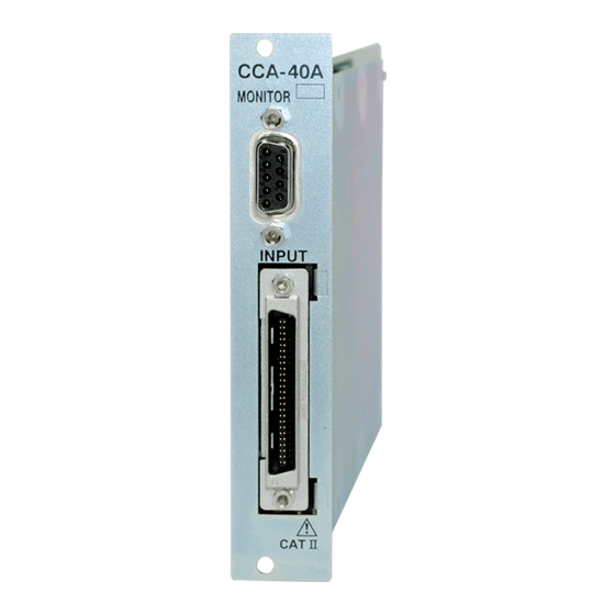
1-5 CONTROLS AND INDICATORS CCA-40A CCA-40A-F 1) Input connector Input connector for 8 channels. Connected to a CCA input cable U-111 (Accessory). 2) Monitor output connector ....Monitor output connector for 8 channels. Monitor output voltage is ±5 V with ± full scale of each range. -
Page 11: Pin Assignment And Connection Of Input Connector
1-6 PIN ASSIGNMENT AND CONNECTION OF INPUT CONNECTOR [Pin Assignment] 25th pin 50th pin Pin assignment of input connectors is described in the following. 1st pin 26th pin Pin Assignment of Input Connectors Pin No. Connection Pin No. Connection CH1 A +12V CH1 G Input COM CH1 E GND CH1 C -Input(-12V) - Page 12 [Connection Method] CCA Input Cable: U-111 (Accessory) Input connector Sensor side connector Insulation cover To connect, hold the plug case, push it into the slot, and then, tightly fasten with screws. To disconnect, unfasten the screws, push in the above portions of item 1) and hold the plug case and pull. Input connector: ........
-
Page 13: The Connection Of The Sensor
(shell portion of a coaxial connector) of the sensor output and the EDX-2000A GND terminal with a tester, etc. Then, connect the sensor to the CCA-40A. If the sensor resistance is less than 5 MΩ, check insulation between the sensor and test target and set it to have more than 5 MΩ. - Page 14 By connecting the low noise cable from the sensor to a sensor side connector of the CCA input cable (Accessory), measurement is available. Sensor Low noise cable CCA input cable insulation Always conduct EDX-2000A Test target Connect GND terminal Put insulation cover of the input to ground cable NOTE...
- Page 15 NOTE The CCA card is equipped with sensor power supply (Constant current source: 4 mA, Applied voltage: Approx. 24 VDC) Take care and always connect appropriate sensors conforming to the specifications or, sensor failure may result in. In addition, take special care that the BNC connector shell of the input cable is applied with voltage of approximately -12 VDC.
-
Page 16: Pin Assignment And Connection Of Monitor Output Connector
1-8 PIN ASSIGNMENT AND CONNECTION OF MONITOR OUTPUT CONNECTOR [Pin Assignment] Pin Assignment Of Monitor Output Connector Signal Name 1st pin CH1 monitor output 6th pin CH2 monitor output 5th pin CH3 monitor output CH4 monitor output 9th pin CH5 monitor output CH6 monitor output CH7 monitor output CH8 monitor output... - Page 17 [Connection Method] Centralized Output Cable U-62 (Optional) Monitor output connector To connect, hold the plug case and push it in. Fasten screws portions of item 1) and fix the cable. To disconnect, unfasten the screws and pull out front the plug case. Monitor output connector: Model XM3B-0942-132L (OMRON made) Centralized output cable U-62:...
-
Page 18: Installation Of Cca Card Board
2) After replacing the conditioner card, power ON the CCA-40As are installed in EDX-2000A and check the startup screen. If the “Card slots 1 and 2. Type” CCA-40A is displayed on the “Slot No.” column, it means that the conditioner card is properly replaced. Slot No. Card Type If “DISABLE”... -
Page 19: How To Set Cca-40A
2. HOW TO SET CCA-40A How to set the CCA card is conducted entirely from the EDX-2000A screen. Settings and measurement of the CCA card are conducted in due order as described in the following table. EDX-2000A Initial Screen ↓... - Page 20 EDX-2000A, CCA-40A appears as the “Card Type” in the “Slot No.” column. (The screen at the right shows that ‘1’ CCA-40A is installed in the slot No. 1) Here, select the item 2) Condition from the main menu and press the ENTER key.
- Page 21 Channel Cond Select item 1) <Channel Cond> from <Condition> main menu to display the screen at the right. Here, point the cursor to the desired item and press the ENTER key. MEAS Channel Select 1) <MEAS Channel> from the <Channel Cond> menu to display the screen at the right with a “MEAS Channel”...
- Page 22 Mode Select 2) <Mode> from the <Channel Cond> menu to display the screen at the right with a “Mode” setting window. For normal use, select 0) Voltage. NOTE Since item 1) “Reserve” is a reserved mode, do not select the “Reserve” mode. Or, no measurement is made for signal output from sensor that is connected to a CH with “Reserve”...
- Page 23 Examples of setting range is described in the following: When the accelerometer sensitivity = 10.20 [mV/m/S ] (100 mV/G, 1 G=9.80665 m/S ) and estimated maximum acceleration = 147.1 [m/S ] (15 G), the estimated maximum input voltage shall be obtained by the following expression.
- Page 24 Sampling frequency range usable for the antialising filter is 100 Hz or more. Although the card type is CCA-40A-F, if “AUTO” is not displayed on the “Low Pass Filter” setting window, check whether or not the sampling frequency is set to less than 100 Hz.
- Page 25 CAL ON/OFF Select 5) <CAL ON/OFF> from the <Channel Cond> menu to display the screen at the right with “CAL ON/OFF” setting window. Here, set the cursor to “ON” or “OFF” and press the ENTER key. Only CHs that are set to “ON” are allowed for entering CAL value when conducting the measurement.
- Page 26 To conduct CAL on the “Measurement" screen (see the right figure), point the cursor to 5) CAL ON/OFF and press the ENTER key. The following operation is repeated every time the ENTER k ey is pressed. Monitoring CAL:ON(+) (CAL OFF) CAL:ON(-) Other Settings For how to set “CAL Coef,”...
- Page 27 NOTE If channel of 20 mV range and that of 5000 mV range are mixedly used in the same card, crosstalk may occur resulting to display a waveform that is different from the input waveform of the channel of 20 mV range. [Reference] <The most affected example>...
- Page 28 NOTE When the CCA card power is ON, when the input connector is disconnected, when the sensor is removed, measuring range is changed, or when excess signal is entered, the output voltage may largely varies. But it is not faulty. Although the time required until the output voltage becomes stable varies according to sensors in use or CCA card measuring range, the output voltage becomes stable in approximately 20 to 40 seconds.
-
Page 29: Specitifications
3. SPECITIFICATIONS 3-1 HARDWARE SPECIFICATIONS Name ..........CCA-40A/CCA-40A-F Charge Amplifier Card (Note) Compatible Sensors ......Piezoelectric Accelerometer (Voltage output type: Insulated case (Note) Output and case(or mounting surface) should be insulated with each other. Number of Measuring CHs ....8 CHs/card Sensor Power Supply ...... -
Page 30: Outside Drawing
3-2 OUTSIDE DRAWING <CCA-40A> <CCA-40A-F>... -
Page 31: Optionals
4. OPTIONALS Input Adaptor: BNCP-C25J-A (The change of BNC and miniature connector) By connecting an input adaptor BNCP-C25J-A to a CCA input cable (U-111), measurement is available with a sensor having miniature connector type cable. #10-32UNEF-2A Centralized Output Cable: U-62 By connecting a centralized output cable U-62 (Length: Approx.
Need help?
Do you have a question about the CCA-40A and is the answer not in the manual?
Questions and answers