Table of Contents
Advertisement
Quick Links
L4063
Rev. B
Paragraph
1.0 . Receiving instructions ..............................................2
2.0 . Safety Issues .................................................................2
3.0 . Product Description...................................................2
4.0 . Safety Information - ATM-4 ....................................3
5.0 . Misalignment Determination Procedure ...........3
6.0 . Installation and Operation ......................................4
7.0 . Rotational or Twist Misalignment ........................5
8.0 . Vertical Operation ......................................................6
09/19
page
10.0 . Inspection and Examination...................................6
11.0 . Storage ...........................................................................6
12.0 . Lubrication and Maintenance ................................6
13.0 . Troubleshooting .........................................................7
14.0 . Application Dimensions ...........................................7
15.0 . Range of Application Tables ...............................8-10
16.0 . Weights and Dimensions ....................................... 11
1
Instruction Sheet
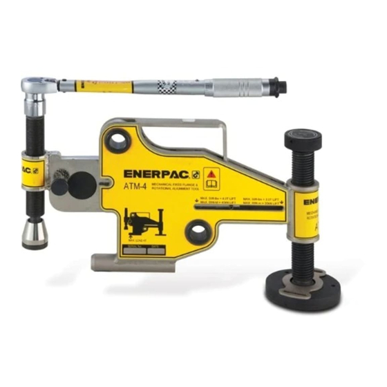
Hydraulic Flange Alignment Tool
Model ATM-4
9.0 . Dismantling the ATM-4 ............................................6
Advertisement
Table of Contents

Summary of Contents for Enerpac ATM-4
-
Page 1: Table Of Contents
2.0 . Safety Issues ..............2 10.0 . Inspection and Examination........6 3.0 . Product Description...........2 11.0 . Storage ................6 4.0 . Safety Information - ATM-4 ........3 12.0 . Lubrication and Maintenance ........6 5.0 . Misalignment Determination Procedure ...3 13.0 . Troubleshooting ............7 6.0 . -
Page 2: Receiving Instructions
2.0 SAFETY ISSUES 3.2 Major Features and Components See Fig. 1. for an overview of ATM-4 major features Failure to comply with the and components. following cautions and warnings could cause equipment damage Fig. -
Page 3: Safety Information - Atm-4
5.0 MISALIGNMENT DETERMINATION PROCEDURE • The ATM-4 MUST NOT be attached to a flanged joint prior to the misalignment determination procedure being carried out. Refer to warning statement in section 4.0. -
Page 4: Installation And Operation
(see Fig. 10). Note: The torque wrench and 22 mm socket supplied with the tool is preset to apply a maximum force of 50 ft. lbs. [68 Nm]. CAUTION: Only use torque wrench supplied with ATM-4. -
Page 5: Rotational Or Twist Misalignment
Fig. 11 3. Insert the bolt into the bolt-hole at Point A (see Rotational or Twist Misalignment Fig. 13) and then release the ATM-4. The load will transfer onto the inserted bolt. The ATM-4, within its 4 Ton [40 kN] maximum 4. -
Page 6: Vertical Operation
Once alignment is achieved, all work on the joint the rollers and bearings for examination. finished, and bolt-up completed (apart from the bolt hole in which the ATM-4 is housed), the tool STEP 4. Inspect the roller shafts, rollers and bearings can be dismantled by reversing steps 1 thru 5 in for damage. -
Page 7: Troubleshooting
PROBLEM 2: THE FRICTION PAD ON THE SWIVEL, the ATM-4 (i.e. 4 Ton [40 kN]). AT THE BASE OF THE SCREW BOLT, ROTATING FLANGE SOLUTION: a. - Page 10 10 10...
-
Page 11: Weights And Dimensions
16.0 WEIGHTS AND DIMENSIONS Note: Weights shown are approximate. WEIGHTS Tool with strap ................19.2 lbs [8,7 kg] Torque wrench and socket . - Page 12 www.enerpac.com...


Need help?
Do you have a question about the ATM-4 and is the answer not in the manual?
Questions and answers