Table of Contents
Advertisement
Quick Links
This manual provides information regarding
5800 Ontario Mills Pkwy
the operation and maintenance of these
Ontario, CA 91764 USA
products. We have made every effort to
www.duromaxpower.com
ensure the accuracy of the information in
this manual. We reserve the right to change
Call our Customer Care Team Toll Free 8-5 PM PST Mon-Fri
844-DUROMAX
this product at any time without prior
notice.
Advertisement
Table of Contents

Related Manuals for DUROMAX XP2000PX


Summary of Contents for DUROMAX XP2000PX
- Page 1 We have made every effort to www.duromaxpower.com ensure the accuracy of the information in this manual. We reserve the right to change Call our Customer Care Team Toll Free 8-5 PM PST Mon-Fri 844-DUROMAX this product at any time without prior notice.
- Page 2 FCC Statement This device complies with Part 15 of the FCC Rules. Operation is subject to the following two conditions: (1)This device may not cause harmful interference. (2)This device must accept any interference received, including interference that may cause undesired operation. Changes or modifications not expressly approved by the party responsible for compliance could void the user’s authority to operate the equipment.
-
Page 3: Table Of Contents
CONTENTS Introduction Introduction ........................4 General Safety Procedures ................... 6 Power Station Setup ..................... 13 Power Station Components Power Station Components ..................14 Package Contents ......................17 Using the Power Station Charging the Power Station Using a Standard Outlet ..........18 Charging the Power Station Using a Car Charger ............. - Page 4 DUROMAX The DuroMax Way is more than just a brand, it is our understanding and appreciation of just how important power can be to someone without it… DUROMAX FOR HOME DUROMAX FOR WORK DUROMAX FOR PLAY Electricity in our home not...
-
Page 5: Introduction
INTRODUCTION DuroMax Power Equipment is headquartered in Ontario, California and is the industry’s leader in Dual Fuel and Tri Fuel portable generator technology. In addition to a full assortment of portable generators ranging from digital inverters to large 16,000-watt generators that can power your whole home, their product line includes power stations, pressure washers, engines, pumps, and accessories. -
Page 6: General Safety Procedures
GENERAL SAFETY PROCEDURES SAFETY ALERT SYMBOL The safety alert symbol is used with one of the safety words (DANGER, WARNING, or CAUTION) to alert you of hazards. Please pay attention to these hazard notices both in this manual and on the power station. Please familiarize yourself with the following safety symbols and words: DANGER: Indicates a hazard that will result in serious injury or death if instructions are not followed. - Page 7 DANGER: This power station generates powerful voltage. Serious injury or even death can occur if these precautions aren’t followed. Always keep your power station in a dry, well-ventilated area when in use. Do not operate the power station with a damaged cord, plug, or damaged output cable.
- Page 8 GENERAL SAFETY PROCEDURES (CONTINUED) WARNING: In case of battery damage: If damaged, the internal battery may emit hazardous fumes. If fumes are present, move Power Station to a well-ventilated area. Do not try to repair the Power Station or replace the battery. WARNING: When operating the power station: Always use in a dry well ventilated area while in use and do not obstruct fan openings on unit.
- Page 9 Do not tamper or disassemble the power station to attempt to service or replace personal injury. For service information please contact our DuroMax technical support team at 844-387-6629. Please have your serial number and model number available when service, repair, or replacement is required.
- Page 10 GENERAL SAFETY PROCEDURES (CONTINUED) WARNING: When charging the power station: Always charge the power station’s internal battery in a well-ventilated area. Do not use the AC charging cable outdoors. Do not expose AC charging cable to oil, oil vapor, grease, gasoline, gasoline vapors, or other caustic substances that may damage the AC charging cable.
- Page 11 Lithium batteries must be charged regularly to perform well. The Power Station must be fully charged at least once every 6 months (180 days).
-
Page 13: Power Station Setup
POWER STATION SETUP Unpack and Prepare the Power Station Place the power station box on a level and sturdy surface. Remove box accessories Remove all the box accessories and cords prior to removing the power station. Lift power station from the box Lift the power station from the box using the top carrying handles on both sides of the power station. -
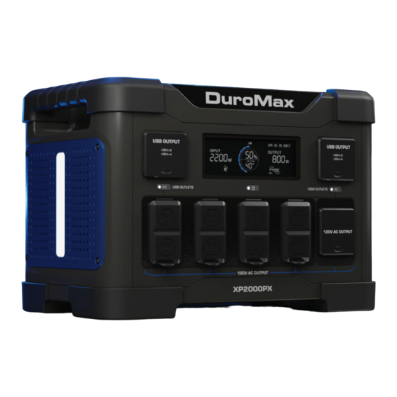
Page 14: Power Station Components
POWER STATION COMPONENTS 4. USB Output Set 2 3. Digital Display 5. AC ON/OFF 8. Back Light 2. Power Button 7. Charging Port 9. Light Control 6. Car/Solar Input 1. USB Output Set 1 10. DC ON/OFF 12. 120V 30A Outlet 11. - Page 15 14. Parallel/Series Connection Ports 13. Wireless Chargers 15. Side Light 10. DC ON/OFF - A digital DC button used to turn the DC power ON or OFF. 11. 120V 20A GFCI Outlets - Use to connect electrical devices that run 120 Volt, 60 Hz, single- phase, AC current (NEMA 5-20).
- Page 16 POWER STATION COMPONENTS (CONTINUED) 13 14 SYMBOL TITLE DESCRIPTION Input Current Displays the real time input power in Watts. Temp Short If the power station detects a short, overload, and/or over- Overload heat, then power output will be cut and this icon will show. Battery Charge Displays the remaining battery capacity percentage of the unit.
-
Page 17: Package Contents
PACKAGE CONTENTS Your power station comes with the items listed below. Please check to see that all of the following items are included with your power station. Parallel Cable Car Charging Cable AC Charger Cable Used to parallel with another Used to charge the power Used to charge the power power station or inverter... -
Page 18: Using The Power Station
USING THE POWER STATION Charging the Power Station Using a Standard Outlet Attach AC charging cord to unit The AC charging cord outlet is located on the back side of the power station. Lift up the charging cord outlet cover and plug in the charging cord. -
Page 19: Charging The Power Station Using A Car Charger
Charging the Power Station Using a Car Charger Attach DC charging cord to unit The DC charging cord outlet is located on the back side of the power station. Lift up the charging cord outlet cover and plug in the charging cord. Ensure that you connect the red wire to the red input and the black wire into the black input. -
Page 20: Charging The Power Station Using A Solar Panel
USING THE POWER STATION (CONTINUED) Charging the Power Station Using a Solar Panel The power station will be compatible with any solar panels rated between 10V-150V with an APP connector. See the below table for recommended solar panels. Recommended Solar Panels Model Watts Bluetti SP120... -
Page 21: Using The Power Station Ac Output
Using the Power Station AC Output Hold the power button The power button is located under the main display. Press and hold the power button for 3 seconds to turn on the power station. Turn on the AC power The AC power button is located on the right side of the main control panel. -
Page 22: Using The Power Station Dc Output
USING THE POWER STATION (CONTINUED) Using the Power Station DC Output Hold the power button The power button is located under the main display. Press and hold the power button for 3 seconds to turn on the power station. Turn on the DC power The DC power button is located on the left side of the main control panel. -
Page 23: Shutting Down The Power Station
Shutting Down the Power Station Unplug all connected devices from the power station. Hold the power button The power button is located under the main display. Press and hold the power button for 3 seconds to turn OFF the power station. WARNING electricity might damage the internal inverter. -
Page 24: Using The Power Station Eco Mode
USING THE POWER STATION (CONTINUED) Using the Power Station ECO Mode Using the ECO mode on the power station will cause the power activate and use ECO mode, see the following instructions: Click the power button twice Click the power button twice in quick succession to activate ECO mode. -
Page 25: Using The Power Station Ups Mode
Using the Power Station UPS Mode The power station is capable of operating as an uninterrupted power supply (UPS) to help keep a steady power supply to sensitive equipment in the event of a power outage. Plug in AC charging cord The AC charging cord outlet is located on the back side of the power station. -
Page 26: Using The Power Stations In Parallel
USING THE POWER STATION (CONTINUED) Using the Power Stations in Parallel The power station is capable of paralleling with another power station of the same model. If connected in parallel the output current will increase to help with larger load items. CAUTION: Do not power the power stations on prior to connecting the parallel cables to avoid damaging the internal inverter. -
Page 27: Parallel Operation With An Inverter Generator
Parallel Operation With an Inverter Generator The power station is capable of paralleling with an inverter generator. If connected in parallel the output current will increase to help with larger load items. CAUTION: Do not power the power station and inverter generator on prior to connecting the parallel cables to avoid damaging the internal inverters. - Page 28 USING THE POWER STATION (CONTINUED) power stations and unplug devices. on each unit for 3 seconds, then unplug the parallel cables.
-
Page 29: Using The Power Station Lights
Using the Power Station Lights Using the back light The light control button for the back light will be located under the back light. • Press the light control button once to turn on low light mode. • Press the light control button two times to turn on medium light mode. - Page 31 SPECIFICATIONS Model Number XP2000PX Battery Capacity 1843.2 Wh Max Power Output 4000W Rated Power Output 2000W Battery Type LiFePO4 Battery Lifespan Battery Cell Voltage 3.2V Battery Cell Capacity 6 Ah Recommended Charging Temperature 32°F to 104°F (0°C to 40°C) Recommended Discharging Temperature 14°F to 104°F (-10°C to 40°C)
-
Page 32: Troubleshooting
Did not hold power button long button for 3 seconds to power turn on enough the unit on Contact DuroMax customer Battery is faulty service at 844-DUROMAX Check your homes main break- Home circuit breaker is tripped er panel and reset the breakers... - Page 33 Mode Description Solution Solar panels are not within Check that your solar panels are rated between 10V-150V Verify that the solar panels are Solar panels improperly properly connected at the connected outlet and fully clipped on the Unit will not charge solar charging cables through solar Check that your solar panels are...
-
Page 35: Warranty
3-Year Warranty or 1000 Cycle Limited Warranty DuroMax warrants to the original purchaser that the components will be free of defects in material and workmanship for a period of three (3) years or 1000 cycles (parts and labor), whichever occurs use. -
Page 37: Customer Service Department
CUSTOMER SERVICE DEPARTMENT DuroMax Power Equipment is committed to ensuring that our products perform when they need to. Our power stations are your lifeline in the event of an emergency. Should you have any problems, please contact our customer service department:... - Page 38 5800 Ontario Mills Parkway Ontario, CA 91764 United States 844-DUROMAX REV: XP2000PX-04012024...
Need help?
Do you have a question about the XP2000PX and is the answer not in the manual?
Questions and answers