Table of Contents
Advertisement
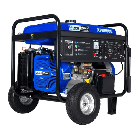
Gasoline Powered Generator
XP6500E and XP8500E
Max Tool Customer Service
customer_service@maxtool.com
or call 1-800-629-3325 (option 3) Monday -Thursday 6am to 7pm, Friday 6am to 5:30pm. PST
Product Support
support@maxtool.com
or call 1-800-629-3325 (option 3) Monday -Thursday 6am to 7pm, Friday 6am to 5:30pm. PST
This manual provides information regarding the operation and maintenance of these products.
We have made every effort to ensure the accuracy of the information in this manual.
We reserve the right to change this product at any time without prior notice.
Owner's Manual
(Product: information, application, service info & warranty questions)
Advertisement
Table of Contents

Related Manuals for DUROMAX XP6500E


Summary of Contents for DUROMAX XP6500E
- Page 1 Gasoline Powered Generator XP6500E and XP8500E Owner’s Manual Max Tool Customer Service customer_service@maxtool.com or call 1-800-629-3325 (option 3) Monday -Thursday 6am to 7pm, Friday 6am to 5:30pm. PST Product Support (Product: information, application, service info & warranty questions) support@maxtool.com or call 1-800-629-3325 (option 3) Monday -Thursday 6am to 7pm, Friday 6am to 5:30pm. PST This manual provides information regarding the operation and maintenance of these products.
- Page 2 FEATURES · Powerful Enough to Run Essential Appliances · During Power Outages · 120 and 240 Volt AC Outputs · 12V DC Output for Automotive Battery Charging · Low Oil Automatic Shutoff · Circuit Breaker for Overload Protection · Max Fuel Tank Capacity ·...
-
Page 3: Table Of Contents
TABLE OF CONTENTS GENERAL SAFETY PROCEDURES………………………………………………………………1 PACKAGE CONTENTS…………………………………………………………………………….4 GENERATOR COMPONENTS……………………………………………………………………..5 PREPARING THE GENERATOR FOR USE..…....………………………………………6 Using the Generator for the First Time........…………………………...6 Step 1-Add Oil.………………………………….…………………………………..6 Step 2- Add Gasoline.…………………………………………………....7 Step 3- Ground the Generator....……………………………………….7 Subsequent Use of the Generator.....…………………………………………..8 Step 1- Check the Oil......……………………………………………..8 Step 2-- Check the Gas Level......……………………………………...8 Step 3- Ground the Generator....………………………………………..8 STARTING THE GENERATOR....……………………………………………………….9... -
Page 4: General Safety Procedures
GENERAL SAFETY PROCEDURES Please familiarize yourself with the following safety symbols and words: The safety alert symbol is used with one of the safety words (DANGER, CAUTION, or WARNING) to alert you to hazards. Please pay attention to these hazard notices both in this manual and on the generator. - Page 5 WARNING: This generator produces powerful voltage, which can result in electrocution. • ALWAYS ground the generator before using it (see the "Grounding the Generator" portion of the "PREPARING THE GENERATOR FOR USE" section). • Generator should only be plugged into electrical devices, either directly or with an extension cord.
- Page 6 In addition to the above safety notices, please familiarize yourself with the safety and hazard markings on the generator.
-
Page 7: Package Contents
PACKAGE CONTENTS Your generator comes with the items listed below. Please check to see that all of the following items are included with your generator. Screw driver Spanner Spark plug wrench... -
Page 8: Generator Components
GENERATOR COMPONENTS Please familiarize yourself with the locations and functions of the various components and controls of your generator. (1) Air cleaner- a removable, cleanable, sponge-like element that limits the amount of dirt pulled into the engine. (2) Choke lever- Adjusts the amount of air let into the engine. (3) Fuel Gauge- Indicates the amount of fuel in the tank. -
Page 9: Preparing The Generator For Use
This amount, which is equal to the oil capacity of the engine crankcase, can be found on the chart in figure 1. When filling the engine with oil in the future, please refer to this chart. Model number XP6500E XP8500E Engine oil capacity 37 fluid oz. -
Page 10: Step 2- Add Gasoline
Gas can age in the tank and make it hard to start up the generator in the future. Never store generator for extended periods of time with fuel in the tank. Model number XP6500E XP8500E Gas tank capacity 25L(6.6 us. gallons) -
Page 11: Step 3- Ground The Generator
Step 3- Ground the Generator WARNING: Failure to properly ground the generator can result in electrocution. Ground the generator by tightening the grounding nut against a grounding wire (see figure 5). A generally acceptable grounding wire is a No. 12 AWG (American Wire Gauge) stranded copper wire. This grounding wire should be connected at the other end to a copper or brass-grounding rod that is driven into the end. -
Page 12: Step 3- Ground The Generator
WARNING: Gasoline and gasoline fumes are highly flammable. ● Do not fill tank near an open flame. ● Always allow the engine to cool for several minutes before refueling. ● Do not overfill (check the "Specifications" section for the tank capacity of your generator). -
Page 13: Using The Generator
The surge wattage ability of the generator covers this extra power requirement. Model Number Rated (Running) Wattage Surge Wattage 5500 6500 XP6500E XP8500E 7000 8500 Figure 9-generator wattage by model number The total running wattage requirement of the electrical devices connected to the generator should not exceed the rated wattage of the generator itself. - Page 14 If these specifications are not available you may estimate the Watts required by your device by using the chart in figure 10. Tool or Appliance Rated (Running) Watts Additional Surge Watts Electric water heater (40 gal) 4000 Hot plate 2500 Saw-radial arm 2000 2000...
- Page 15 Once you have determined what electrical devices you will be powering with the generator, connect these devices according to the following procedure: 1. Plug in each electrical device with the device turned off. NOTE: Be sure to attach appliances to the correct receptacle (outlet). Connect standard 120 Volt, single phase, 60 Hz loads only to the 120 Volt receptacle.
-
Page 16: Dc Usage
Device Requirements Max. Cord Length (ft) by Wire Gauge Watts Watts Amps #8 wire #10 wire #12 wire #14 wire #16 wire (120V) (240V) 1000 1200 1800 1200 2400 1800 3600 2400 4800 3000 6000 3600 7200 4800 9600 *NR= not recommended Figure 12-Maximum Extension Cord Lengths by Power Requirement DC Usage CAUTION:... -
Page 17: Stopping The Generator
STOPPING THE GENERATOR To stop the generator: 1. Turn off, then unplug all connected electrical devices. 2. Switch the circuit breaker to the "off' position. 3. Allow the generator to run for several more minutes with no electrical devices connected. This helps stabilize the temperature of the generator. 4. -
Page 18: Checking The Oil
13. When the oil level is low you will need to add oil until the level is sufficient to run the generator. The oil capacity of your generator engine is listed in figure 15. Model number XP6500E XP8500E Engine oil capacity 37 fluid oz. -
Page 19: Air Cleaner Maintenance
It is only necessary to drain the oil from the crankcase, other than for regular oil changes, if it has become contaminated with water or dirt. In this case, you can drain the oil from the generator according to the following steps: 1. -
Page 20: Fuel Filter Cup Cleaning
Figure 18- Removing the air cleaner casing. Fuel Filter Cup Cleaning The fuel filter cup is a small well underneath the fuel valve. It helps to trap dirt and water that may be in your fuel tank before it can enter the engine. To clean the fuel filter cup: 1. -
Page 21: Emptying The Gas Tank
6. Screw the spark plug back into its place on the generator using the spark plug wrench. Replace the spark plug cap. Emptying the Gas Tank Before storing your generator for extended periods of time, you should drain your generator of gasoline. -
Page 22: Specifications
GENERATOR SPECIFICATIONS AC Output XP6500E XP8500E Rated Wattage 5500W 7000W Surge Wattage 6500W 8500W Rated Voltage 120/240V 120/240V Rated Frequency 60Hz 60Hz Phase Single Single DC Output XP6500E XP8500E Voltage Amperage 8.3A 8.3A Length=28 Length=28 Width=20+ Dimensions (in): Width=20 Height=21.3 Height=21.3... -
Page 23: Generator Assembly And Mounting
Move generator to a level surface to Generator is not on level prevent shutdown from surface. triggering. Oil is low Add or replace oil. Set the circuit breaker to the “on” Circuit breaker is off. position. Engine runs but If you are using an extension cord, there is no Bad connecting wires/cables. - Page 24 Figure 25 Figure 26 Figure 27 Figure 28 CHANGE THE CARBON-BRUSH...
- Page 25 CHANGE THE AVR...
-
Page 26: Wiring Diagram
WIRING DIAGRAM(XP6500E/XP8500E) -
Page 27: Exploded View And Parts List
EXPLODED VIEW AND PARTS LIST(XP6500E/XP8500E) - Page 28 Item Part Description Item Part Description DJ188F-16121-C Starter comp, recoil DJ190FD-14100-A Carburetor assy. GBT5789-B6-8 Flange bolt M6×8 DJ188F-14003-B Packing, carburetor DJ188F-16120-A Fan, cover comp DJ188FD-14004-A Insulator, carburetor GBT5789-B6-12 Flange bolt M6×12 GBT6177/10-N-6 Flange nut M6 DJ188F-11012-A Shroud comp DF6500H-14205-A Stay, air cleaner DJ168F-11039-A Clip.
- Page 29 DJ168F-13204-A Nut, pivot adjusting DJ190F-12001-B Piston GBT16674-B8-40 DJ190F-12002-A Pin, piston Flange bolt M8×40 DJ188FD-11001-B Crankcase cover DJ190F-12200-B Connecting rod assy. GBT818-S5-10 Flange bolt M5×10 DJ188FD-15200-A Control assy. DF3800H-11032-A Fan cover DJ188F-15007-A Spring, governor DJ188F-11007-A Cap assy. oil filler DJ188F-15008-A Spring, throttle return DJ188F-15100-A Governor kit DJ188F-15004-B...
- Page 30 EXPLODED VIEW AND PARTS LIST(XP8500E)
- Page 31 Item Part Qty Description Item Part Qty Description Gasoline engine DF6500H-31073-A Handle Head DF8000H-33013-A Flange bolt DF6500H-31074-A Gasket, handle DF3800H-33005-A Generator Stay DF6500H-31058-F Hand push F DF8000H-33003-A Bolt DF6500H-31058-A Hand push A Plain washer Ф 10 GB/T97.1-1987 GBT16674-B8-45 Bolt, handle M8×45 GB/T2776-1994 Bearing 6204DU GBT6183-N-8...
- Page 32 EXPLODED VIEW AND PARTS LIST(XP6500E)
- Page 33 34217-001 Current sensor DF3800H-14416-B Inner Hood DFD6500H-34213-001 Wire DF3800H-14403-A Side Hood 34225 Charger GBT5789-B6-16 Bolt M6 x 16 34226-001 lamp XP6500E-31100-A Frame comp 34203-005 Idle control switch DF3800H-31201-A Bottom rubber A 189 34202-001 Voltage selector DF3800H-31202-A Bottom rubber GB6183-N-8 Flange nut M8...
Need help?
Do you have a question about the XP6500E and is the answer not in the manual?
Questions and answers