Table of Contents
Advertisement
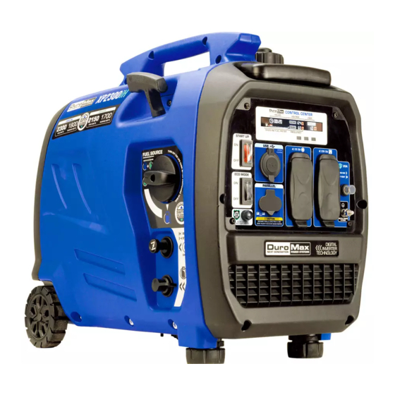
XP2300IH INVERTER GENERATOR
User Manual
REV: XP2300iH-02032021
5800 Ontario Mills Pkwy
Ontario, CA 91764 USA
This manual provides information regarding the operation
www.DuroMaxpower.com
and maintenance of these products. We have made every
effort to ensure the accuracy of the information in this
Call our Customer Care Team Toll Free 8-5pm PST Mon-Fri
manual. We reserve the right to change this product at
844-DuroMax
any time without prior notice.
Advertisement
Table of Contents
Troubleshooting

Related Manuals for DUROMAX XP2300IH


Summary of Contents for DUROMAX XP2300IH
- Page 1 XP2300IH INVERTER GENERATOR User Manual REV: XP2300iH-02032021 5800 Ontario Mills Pkwy Ontario, CA 91764 USA This manual provides information regarding the operation www.DuroMaxpower.com and maintenance of these products. We have made every effort to ensure the accuracy of the information in this Call our Customer Care Team Toll Free 8-5pm PST Mon-Fri manual.
-
Page 3: Table Of Contents
CONTENTS Introduction Introduction ........................6 General Safety Procedures ................... 8 Quick Start Guide (Gasoline) ..................14 Quick Start Guide (Propane) ..................16 Generator Components ....................18 Package Contents ......................20 Generator Setup Adding Oil ........................22 Adding Gasoline ......................23 Grounding the Generator ................... - Page 4 CONTENTS Maintenance and Care Maintenance Schedule ....................40 Maintenance Log ......................41 Checking the Oil ......................42 Changing the Oil ......................43 Cleaning the Air Filter ....................44 Spark Plug Maintenance ....................46 Storage and Transportation ..................48 Specifications ........................49 Troubleshooting Basic Troubleshooting ....................
- Page 6 DuroMax The DuroMax Way is more than just a brand, it is our understanding and appreciation of just how important power can be to someone without it… DuroMax FOR HOME DuroMax FOR WORK DuroMax FOR PLAY Electricity in our home not...
-
Page 7: Introduction
INTRODUCTION DuroMax Power Equipment is headquartered in Ontario, California and is the industry’s leader in Dual Fuel portable generator technology. In addition to a full assortment of portable generators ranging from digital inverters to large 15,000-watt portable standby units, their product line includes pressure washers, engines, pumps, and accessories. -
Page 8: General Safety Procedures
GENERAL SAFETY PROCEDURES SAFETY ALERT SYMBOL The safety alert symbol is used with one of the safety words (DANGER, CAUTION, or WARNING) to alert you of hazards. Please pay attention to these hazard notices both in this manual and on the generator. Please familiarize yourself with the following safety symbols and words: ●... - Page 9 WARNING: This generator may emit highly flammable and explosive gasoline vapors, which can cause severe burns or even death. A nearby open flame can lead to an explosion even if not directly in contact with gasoline. ● Do not operate near an open flame. ●...
- Page 10 UNIT AND PURCHASE INFORMATION Serial Number Serial Number The serial number is located on the engine block, above and to the left of the oil fill. Serial number format The serial number will be shown in two parts. The engine model, followed by the serial number.
- Page 11 As the only safe way to use a portable generator, taking your generator outside is absolutely mandatory to keep your family safe from carbon monoxide. But there’s even more you can do. By educating yourself about all carbon monoxide risks, you’ll be better prepared to protect your family from this colorless, odorless threat.
- Page 13 QUICK START The quick start of your generator is the minimum necessary setup that will get you going as soon as possible. Be sure to read the instructions for full setup instructions.
-
Page 14: Quick Start Guide (Gasoline)
QUICK START GUIDE (GASOLINE) Add oil The oil fill cap is located on the lower engine block to the right of the recoil start housing. Remove the oil fill cap and fill with 10w30 oil. Add gasoline The fuel cap is located on top of the fuel tank. Fill the tank with fresh unleaded gasoline 87 octane or higher. - Page 15 Turn start switch on The start switch is located on the left side of the front power panel next to the low Idle. Press the switch up to the start position to allow the generator to start. Turn Low Idle off Turn low idle off The Low Idle is located on the left side of the front power The low Idle is located on the left side of the front power...
-
Page 16: Quick Start Guide (Propane)
QUICK START GUIDE (PROPANE) Add oil Add oil The oil fill cap is located on the lower engine block to the The oil fill cap is located on the lower engine block to the right of the recoil start housing. Remove the oil fill cap and right of the recoil start housing. - Page 17 Turn Low Idle off Turn low idle off The Low Idle is located on the left side of the front power The low idle is located on the left side of the front power panel, next to the breaker. Flip the switch down to disable panel, next to the parallel outlet.
-
Page 18: Generator Components
GENERATOR COMPONENTS 6. Fuel Valve 4. Recoil Start 5. Fuel Cap 7. Handle 8. Power Panel 3. Fuel Switch 2. Choke 1. Wheels 9. LPG Inlet 1. Wheels - Solid wheels allow for easy transportation over any terrain. 2. Choke - Assist the generator when starting on gasoline. 3. - Page 19 13. Multimeter 12. USB Ports 11. Start Up Switch 10. Low 14. Breaker Idle 15. Ground 18. Parallel Ports 17. 3-Prong 16. 120v GFCI Twist-Lock 13. Multimeter - Provides information of Hours Run, Voltage, Hertz, current load on the generator measured in kW, and the amount of gasoline in the gas tank.
-
Page 20: Package Contents
PACKAGE CONTENTS Your generator comes with the items listed below. Please check to see that all of the following items are included with your generator. Double Sided Oil Funnel w/ hose Spark Plug Wrench Screw Driver Used to add oil to the generator without messy spills. -
Page 21: Generator Setup
GENERATOR SETUP Proper setup of your generator will get you going as soon as possible while making sure you and your equipment are safe and cared for. -
Page 22: Adding Oil
. You must add the proper amount of oil before operating the generator for the first time. This amount is equal to the oil capacity of the engine crankcase: Model Number XP2300iH Engine Oil Capacity 13 fl. oz (0.4L) WARNING: Do not apply engine oils with additives or 2-stroke gasoline engine oils. They don’t have enough lubrication and may shorten the engine’s service life. -
Page 23: Adding Gasoline
The fuel gauge on the digital display indicates how much gasoline is in the generator’s gas tank. Replace fuel cap and wipe up any spilled gasoline with a dry cloth. Model Number XP2300iH Gas Tank Capacity 1.1 US Gal. (4.2L) DANGER DO NOT OVERFILL 1.5”... -
Page 24: Grounding The Generator
GENERATOR SETUP (CONTINUED) Step 4 - Grounding the Generator Attach grounding wire Ground the generator by tightening the grounding nut against a grounding wire. Connect the other end to a copper or brass grounding rod that’s driven into the earth. A generally acceptable grounding wire is a No. -
Page 25: Starting The Generator
STARTING THE GENERATOR If this is not your first time using the generator there are still steps you should take to prepare it for operation each time you use it. IMPORTANT: At this point, you should be familiar with the procedures described in the first portion of this section entitled “GENERATOR SETUP”... -
Page 26: Checking The Oil
(see “Adding Oil” portion of the “Maintenance” section). Be sure to replace the cap when finished checking oil. Model Number XP2300iH Engine Oil Capacity 13 fl. oz (0.4L) -
Page 27: Check The Gas Level
Step 2 - Check the gas level (Optional) Check fuel level If running the engine on gasoline check to see that there is sufficient gasoline in the fuel tank. The fuel gauge on the digital display will indicate how much fuel is in the gas tank. DANGER DO NOT OVERFILL 1.5”... -
Page 28: Starting The Generator Using Gasoline
STARTING THE GENERATOR Starting the generator using gasoline Select gasoline fuel The fuel selector is located on the top of the fuel selection panel. Turn the selector counterclockwise to select gasoline. Turn gas valve on The gas valve is located on the gas cap. Rotate the valve clockwise to the ON position. - Page 29 Turn low idle off The low idle is located on the left side of the front power panel. Flip the switch down to disable eco mode when starting the generator. Pull the recoil start The recoil start is located above the fuel panel. Pull the recoil start briskly to start the generator.
-
Page 30: Starting The Generator Using Propane
STARTING THE GENERATOR (CONTINUED) Starting the Generator Using Propane Connect propane hose The LPG inlet is located on the bottom of the fuel selection panel. Connect the propane hose to both the inlet and the propane tank. Open the propane tank. Select LPG fuel The fuel selector is located on the top of the fuel selection panel. - Page 31 Turn low idle off The low idle is located on the left side of the front power panel. Flip the switch down to disable eco mode when starting the generator. Decompress The decompression valve is located on the propane hose. Press the button for 3 - 5 seconds to release any air int he line.
- Page 32 STARTING THE GENERATOR (CONTINUED) Starting the Generator Using Propane WARNING: WHEN USING THE GENERATOR WITH LPG, MAKE SURE THERE IS NO POSSIBLE IGNITION SOURCE CLOSE TO THE GENERATOR. 1. Before using, make sure all of the LPG connectors and hoses are well connected and sealed.
-
Page 33: Using The Generator
USING THE GENERATOR If this is not your first time using the generator, there are still steps you should take to prepare it for operation each time you use it. IMPORTANT: At this point, you should be familiar with the procedures described in the first portion of this section entitled “GENERATOR SETUP”;... -
Page 34: Ac Usage
USING THE GENERATOR AC Usage ● You may connect electrical devices running on AC current according to their wattage requirements. ● The chart below shows the rated and surge wattage of your generator according to its model number. ● The rated wattage corresponds to the maximum wattage the generator can output on a continuous basis. - Page 35 Tool or Appliance Rated (Running) Watts Additional Surge Watts Electric water heater (40 gal) 4000 Hot plate 2500 Radial arm saw 2000 2000 Electric Stove 1500 Circular Saw 1500 1500 Air compressor (1 HP) 1500 3000 Window air conditioner 1200 1800 Miter saw 1200...
-
Page 36: Connecting A Load To The Generator
USING THE GENERATOR (CONTINUED) Connecting a load to the generator NOTE: Be sure to attach devices to the correct receptacle (outlet). 120v devices can be directly connected to the 120v ONLY receptacles. ● CAUTION: Do not connect 50Hz or 3-phase loads to the generator. Plug in devices Plug in devices to the appropriate receptacle. - Page 37 Choosing the right power cord Long or thin cords can drain the power provided to an electrical device by the generator. When using such cords, allow for a slightly higher rated wattage requirement for the electrical device. See table below for recommended cords based on the power requirement of the electrical device. DEVICE REQUIREMENTS WIRE GAUGE BY LENGTH (ft.) AMPS...
-
Page 38: Parallel Usage
USING THE GENERATOR (CONTINUED) Parallel Usage Connect Ground Connect one side of the green cable to the ground bolt found in the lower right corner of the panel of generator 1. Connect Positive Connect the corresponding red cable to the red parallel port on the front panel of generator 1. -
Page 39: Maintenance And Care
MAINTENANCE AND CARE Proper maintenance and storage of your generator are essential to ensure trouble-free use of your generator when you need it. By following the maintenance and care requirements, you can keep your generator running smoothly and efficiently for years to come. -
Page 40: Maintenance Schedule
MAINTENANCE AND CARE Proper routine maintenance of your generator is essential for safe, economical, and trouble-free operation. It will also help reduce air pollution. WARNING: Improper maintenance, or failure to correct a problem before operation, can cause a malfunction in which you can be seriously injured or killed. Always follow the inspection, maintenance recommendations, and schedules in this instruction manual. -
Page 41: Maintenance Log
MAINTENANCE LOG Date Generator Hours Maintenance Performed... -
Page 42: Checking The Oil
(see “Adding Oil” portion of the “Maintenance” section). The oil will be visible in the oil fill spout when full. Be sure to replace the cap when finished checking oil. Model Number XP2300iH Engine Oil Capacity 13 fl. oz (0.4L) -
Page 43: Changing The Oil
Changing the oil Worn out or dirty oil does not cool the generator properly and can lead to catastrophic engine damage. In addition to regular oil changes, it is necessary to drain the oil from the crankcase if it has become contaminated with water or dirt. -
Page 44: Cleaning The Air Filter
MAINTENANCE AND CARE (CONTINUED) Cleaning the air filter Routine maintenance of the air cleaner helps maintain proper airflow to the carburetor. Check that the air cleaner is free of excessive dirt after every use. Note: Improper maintenance may cause less air to enter the engine or dirty air to enter the engine causing overheating and engine wear. - Page 45 Dry cleaner element Pat dry on a dry cloth and allow the elements to dry completely. Add engine oil to elements Soak the dry elements in a small amount of engine oil. Ring out any excess oil. Replace elements in casing Replace the sponge-like elements in the air cleaner casing and replace the cover.
-
Page 46: Spark Plug Maintenance
MAINTENANCE AND CARE (CONTINUED) Spark Plug Maintenance The spark plug is important for proper engine operation. A good spark plug should be intact, free of deposits, and properly gapped. SPARK PLUG CONSULT MANUAL Improper maintenance may cause reduced fuel economy, BEFORE REMOVING misfires, trouble starting, or damage to the spark plug threads. - Page 47 Measure plug gap Measure the plug gap with a gauge. The gap should be 0.7-0.8 mm (0.028-0.031 in). Clean and re-gap If you are re-using the spark plug, use a wire brush to clean any dirt from around the spark plug base and then re-gap the spark plug.
-
Page 48: Storage And Transportation
MAINTENANCE AND CARE (CONTINUED) Storage and Transportation CAUTION: Never place any type of storage cover on the generator while it is still hot. When transporting your generator: ● Disconnect the spark plug. ● Do not obstruct any ventilation openings & keep the generator in a cool dry area. Storage Period Storage Preparation Allow the unit to run 3 - 5 minutes. -
Page 49: Specifications
SPECIFICATIONS AC Rated Wattage (Gasoline) 1800W AC Rated Wattage (Propane) 1700W AC Surge Wattage (Gasoline) 2300W AC Surge Wattage (Propane) 2150W AC Rated Voltage 120V AC Rated Frequency 60 Hz AC Phase Single DC Voltage DC Amperage Engine Type 4-Stroke OHV Forced-Air Ignition System Non-Contact Transistor Displacement... -
Page 51: Troubleshooting
TROUBLESHOOTING This section of the manual is to help you troubleshoot problems with your generator. -
Page 52: Basic Troubleshooting
TROUBLESHOOTING Mode Description Engine switch is in the OFF po- Turn engine switch to the ON sition. position. Stale gasoline or water in gaso- Drain entire system and refill line. with fresh fuel. Engine is out of fuel Add fuel Fuel is old or contaminated Change fuel Will not start... -
Page 54: Warranty
OEM parts. Warranty Limitations DuroMax Power Equipment does not claim or hold any obligation to loss of time, freight charges, use of the product, or any incidental damages from the use of this product. THIS WARRANTY IS IN LIEU OF ALL OTHER WARRANTIES, EXPRESSED OR IMPLIED. - Page 55 Equipment cannot deny warranty solely for the lack of receipts or for your failure to ensure the performance of all scheduled maintenance. As the small off-road engine owner, you should, however, be aware that DuroMax Power Equipment may deny you warranty coverage if your small off-road engine or a part has failed due to abuse, neglect, improper maintenance or unapproved modifications.
- Page 56 If the part fails prior to the first scheduled replacement, the part must be repaired or replaced by DuroMax Power Equipment according to Subsection (4) below. Any such part repaired or replaced under warranty must be warranted for the remainder of the period prior to the first scheduled replacement point for the part.
- Page 57 (iii) Distribution manifold. (6) Catalyst or Thermal Reactor System (i) Catalytic converter. (ii) Thermal reactor. (iii) Exhaust manifold. DuroMax Power Equipment will furnish with each new engine written instructions for the maintenance and use of the engine by the owner...
-
Page 58: Contact Information
CUSTOMER SERVICE DuroMax Power Equipment is committed to ensuring that our products perform when they need to. Our generators are your lifeline in the event of an emergency. Should you have any problems, please contact our customer service department: DuroMax POWER EQUIPMENT... - Page 60 5800 Ontario Mills Parkway Ontario, CA 91764 United States 844-DuroMax REV: XP2300iH-02032021...
Need help?
Do you have a question about the XP2300IH and is the answer not in the manual?
Questions and answers
how do I replace the CO detector?
access door for oil will not open