
Subscribe to Our Youtube Channel
Related Manuals for Tescom MTI600


Summary of Contents for Tescom MTI600
- Page 1 MTI600 MODULAR 60-600kVA 3 Phase Input-3 Phase Output USER MANUAL Modular UPS 60-600kVA User Manual...
- Page 2 Modular UPS 60-600kVA User Manual...
-
Page 3: Users
Preface Usage This manual introduces the main features, performance, working principle of the new generation modular intelligent UPS and provides users with information on installation, use, operation and maintenance. Users Technical support engineer Maintenance engineer Note Our company is providing a full range of technical support and service. Customers can contact our local office or customer service center for help. -
Page 4: Table Of Contents
Content Preface ............................I Usage ..........................I Users ..........................I Note 1. Safety Precautions ....................... 5 Safety Message Definition ....................5 Warning Label ........................5 Safety Instruction ......................5 Move & Installation ......................6 Debug & Operate ......................6 Maintenance & Replacement .................... 6 Battery Safety ........................ - Page 5 3.3.2. Use Seismic fixed device to fix cabinet ..........20 3.4. Battery ........................22 3.5. Cable Entry ......................22 3.6. Power Cables ......................24 3.6.1. Specifications ..................24 3.6.2. Specifications for Power Cables Terminal ..........25 3.6.3. External Circuit Breaker ................25 3.6.4.
- Page 6 6.1.4. Battery maintenance ................60 7. Product Specification......................62 7.1. Applicable Standards....................62 7.2. Environmental Characteristics ................62 7.3. Mechanical Characteristic ..................63 7.4. Electrical Characteristics ..................63 7.4.1. Electrical Characteristics (Input Rectifier) ..........63 7.4.2. Electrical Characteristics (Intermediate DC Link) ........64 7.4.3.
-
Page 7: Safety Precautions
Safety Precautions 1. Safety Precautions Before handling, installation, operation, maintenance, please read the instruction manual carefully and follow all safety precautions in the manual. If neglected, it may cause personal injury or equipment damage, or even death. The Company will not be liable for injuries and equipment damage caused by your company or your company's customers not following the safety precautions in the instruction manual. -
Page 8: Move & Installation
Safety Precautions Move & Installation Keep the equipment away from heat source or air outlets. Use dry powder extinguisher only, liquid extinguisher can result in electric shock. Do not install the UPS on flammable materials and avoid close contact or adhesion of flammable materials by the UPS. -
Page 9: Battery Safety
Safety Precautions Battery Safety All the battery maintenance and servicing procedures involving internal access need special tools or keys and should be carried out only by trained personnel. WHEN CONNECTED TOGETHER, THE BATTERY TERMINAL VOLTAGE WILL EXCEED 400Vdc AND IS POTENTIALLY LEATHAL. ... -
Page 10: Overview
Overview 2. Overview 2.1. Product Description This Modular UPS is an online double-conversion UPS that uses digital signal processing (DSP) technology. Provide a stable and uninterrupted power supply for the important load. It can eliminate "power pollution" such as power surge, instantaneous high voltage, low voltage, wire noise and frequency offset on the mains, and provide customers with high-efficiency, high-power density power supply guarantee. -
Page 11: Operating Mode
Overview Output Input Rectifier Inverter AC/DC DC/AC Battery Bi-direction DC_DC converter Figure 2-2 Power module diagram 2.4. Operating Mode UPS system adopts online double-conversion design, according to different working conditions, can work in different working modes, including normal mode, battery mode, bypass mode, maintenance bypass mode, ECO mode, auto-restart mode and frequency converter mode. -
Page 12: Combined Power Supply Mode
Overview returns to “normal mode” without interruption. The working principle of the “battery mode” is as follows: Manual Bypass Static Bypass Bypass Output Main Rectifier Inverter AC/DC DC/DC DC/AC Output breaker Bi-direction DC_DC Battery converter Figure 2-4 UPS conceptual diagram in Battery mode Note With the function of Battery cold start, the UPS may start without utility (The battery has been charged). -
Page 13: Maintenance Bypass Mode
Overview bypass static switch. In bypass mode, load power supply quality is not protected by the UPS and may be affected by power failure, abnormal voltage waveform or frequency. As Figure 2-6 shows: Maintenance Bypass Static Bypass Bypass Output Main Rectifier Inverter AC/DC... -
Page 14: Eco Mode
Overview 2.5.5. ECO Mode ECO mode is an UPS energy-saving mode which can be set through the LCD or background software. In ECO mode, when the bypass input voltage is within the ECO range, the load is powered by utility through bypass static switch, the rectifier and inverter are standby. When the bypass input voltage exceeds the ECO voltage range, the load will be switched from the bypass power supply to the inverter power supply, and the UPS will work in normal mode. -
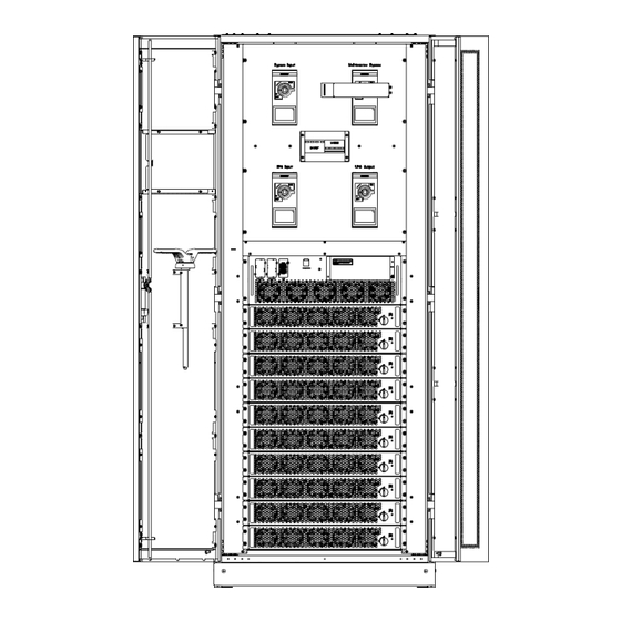
Page 15: Ups Structure
Overview 2.6.2. UPS Structure The UPS structure (front view) is shown in Figure 2-9, back view as Figure 2-10: Figure 2-9 UPS Cabinet front view Modular UPS 60-600kVA User Manual... - Page 16 Overview Figure 2-10 UPS Cabinet back view Modular UPS 60-600kVA User Manual...
-
Page 17: Installation
Installation 3. Installation 3.1. Location 3.1.1. Installation Environment ⚫ The UPS is intended for indoor installation and uses forced convection cooling by internal fans. Please make sure there is enough space for the UPS ventilation and cooling. ⚫ Keep the UPS far away from water, heat and inflammable and explosive, corrosive material. Avoid installing the UPS in the environment with direct sunlight, dust, volatile gases, corrosive material and high salinity. - Page 18 Installation Figure 3-1 Dimensions of Cabinet (unit: mm) Figure 3-2 Reserved Cabinet Space (unit: mm) Ensure that the floor or installation platform can bear the weight of the UPS cabinet, batteries, and battery racks. The weight of batteries and battery racks depends on the site requirements. The Modular UPS 60-600kVA User Manual...
-
Page 19: Unloading And Unpacking
Installation weight for the UPS cabinet is shown in Table 3-1. Table 3-1 Weight of the UPS Item Weight 600kVA cabinet 353kg (Not include bypass and power module) 600kVA Monitoring & Bypass module 52kg 60kVA Power module 36kg 3.2. Unloading and Unpacking 3.2.1. - Page 20 Installation VELCRO Figure 3-4 Disassemble the box Step 4: Remove the protective foam around the cabinet as Figure 3-5: Figure 3-5 Remove the protective foam Modular UPS 60-600kVA User Manual...
-
Page 21: Positioning
Installation Step 5: Check the UPS 1. Visually examine if there are damages to UPS during transportation. If any, contact to the carrier. 2. Check the delivery packing list to see if the accessories are complete and correct. If you find that the attachment is missing or the model does not match, you should timely make on-site records and contact our local office. -
Page 22: Use Seismic Fixed Device To Fix Cabinet
Installation The steps to position the cabinet is as follows: Ensure the supporting structure is in good condition and the mounting floor is smooth and strong; Push the cabinet to the installation point by forklift; Fixed on the ground or channel steel through the bottom hole of the cabinet; Ensure the four anchor bolts are in the same height and the cabinet is fixed and immovable;... - Page 23 Installation Ground Installation Ensure that the installation ground is smooth. Determine the installation position of the cabinet, and draw installation holes on the installation surface according to the seismic fixed device and equipment size diagram. The seismic fixed device and equipment dimension diagram is shown in Figure 3-8: Figure 3-8 Dimensional drawings of seismic fixed device Drill holes on the installation holes of the expansion bolts on the left and right sides of the cabinet using an impact drill, and then tap the expansion pipes of 16nos M14 expansion bolts...
-
Page 24: Battery
Installation Channel steel installation According to the seismic components and equipment dimension diagram, install the channel steel, it is recommended that the width of the channel steel should be more than 50mm, and the channel steel surface should be flush with the ground, and should not be tilted. Determine the bolt mounting holes on the channel steel. - Page 25 Installation Figure 3-10 Diagram of Top Cable Entry Modular UPS 60-600kVA User Manual...
-
Page 26: Power Cables
Installation Figure 3-11 Diagram of bottom Cable Entry 3.6. Power Cables 3.6.1. Specifications The selection of UPS system power cable should meet the 3B in IEC60950-1, and select suitable cable in combination with practical engineering applications, maximum UPS operating current shows in Table 3-2. -
Page 27: Specifications For Power Cables Terminal
Installation verified by referring to IEC60364-5-52 and local relevant specifications. The current values in the table are for data with a rated line voltage of 380V. For a rated voltage of 400V, the current value needs to be multiplied by 0.95; for rated voltage of 415V, the current value needs to be multiplied by 0.92. - Page 28 Installation Step 2: Open the front door of the cabinet (10-slot Cabinet opens the back door), remove the plastic cover. The input and output terminal, battery terminal and protective earth terminal are shown in Figure 3-12: M16 Screw Modular UPS 60-600kVA User Manual...
-
Page 29: Control And Communication Cables
Installation M16 Screw Figure 3-12 Connections terminals Step 3: Connect the input ground wire to the input ground terminal. Note that the ground wire connection must comply with local and national regulations; Step 4: Connect the AC main input cable to the input terminal (mA, mB, mC, N); Connect the AC bypass input cable to the bypass input terminal (bA, bB, bC, N);... -
Page 30: Dry Contact Interface
Installation Figure 3-13 System Communication Interface 3.7.1. Dry Contact Interface Dry contact interface includes EPO, NTC, IP, OP, as it is shown in Figure 3-14, the interface function can be set by software, the function of the dry contact are shown in Table 3-5: Figure 3-14 Dry Contact Interface Table 3-5 Functions of the port Port... - Page 31 Installation Internal Input dry contact, function is settable IP-IP4 Silence Default: Mute the alarm IP-GND GND_DRY Ground for +24V Internal Output dry contact, (Normally open) function is settable OP-NO1 BCB Drive_NO Default: Battery CB trip signal (Valid under EOD or EPO) Internal Output dry contact, (Normally close) function is settable OP-NC1...
- Page 32 Installation OP-5 COM port, optional external VCC and OP-COM internal power supply 24V OP-4 COM port, optional external VCC and OP-COM internal power supply 24V Note The function of each port can be set by the monitor software. The default functions of each port are described as follows. Battery and Ambient Temperature Detection Dry Contact Interface The input dry contact NTC can detect the ambient temperature of batteries and environment respectively, which can be used in environment monitoring and battery temperature compensation.
- Page 33 Installation Figure 3-16 Diagram of input port for remote EPO Table 3-7 Description of input port for remote EPO Port Name Function Trigger EPO when disconnect with EPO-NC REMOTE_EPO_NC J4-2 EPO-24V 24V_DRY +24V EPO-NO REMOTE_EPO_NO Trigger EPO when shorted with J4-3 When UPS system in normal operation, port EPO-NC to EPO-24V should be shorted circuit, and EPO-NO to EPO-24V should be open.
- Page 34 Installation Battery Warning Output Dry Contact Interface The default function of OP-1 is the output dry contact interface, default as the battery CB trip signal (under EOD or EPO). An auxiliary dry contact signal will be activated via the isolation of a relay to trip the CB.
-
Page 35: Communication Interface
Installation Table 3-10 Utility failure warning dry contact interface description Port Name Function Mains failure warning relay (normally closed) OP-NC4 UTILITY_FAIL_NC will be open during warning Mains failure warning relay (normally open) OP-NO4 UTILITY_FAIL_NO will be closed during warning OP-GND Output dry contact GND Overload Alarm Input Dry Contact Interface The default function of OP-4 is the output dry contact interface for overload alarm, when the ups... -
Page 36: Control And Display Panel
Control and Display Panel 4. Control and Display Panel 4.1. Cabinet Display panel The panel is located on the front door. According to the function, it can be divided into two parts: control button and LCD display area; the structure is shown as Figure 4-1: 1: Screen power indicator light 2: EPO switch 3: LCD touch screen... - Page 37 Control and Display Panel Status Operation Information Alarm Figure 4-2 Home page The home page mainly includes status information, information display, state of operation, alarm display, and main menu. ⚫ Status bar The Status bar contains the model of the product; Parallel operational mode and the number of the power module, the time of the system and user account login.
-
Page 38: Main Menu
Control and Display Panel Home Scope Cabinet Module Setting Operate Output voltage Bypass Input Warning Date & Time Mute Output current Main Output History log Fault clear Language Bypass voltage Output Load Comm. Manual bypass Transfer to Load Info. User inverter Manual dust Battery... - Page 39 Control and Display Panel Submenu Infor. Version Figure 4-4 Cabinet Submenu The Cabinet comprises sectors of title, information display, version running status, information of submenu. The sectors are described as follows: ⚫ Title Indicate that the bypass of the cabinet is selected. ⚫...
- Page 40 Control and Display Panel (e) Battery Figure 4-5 Submenu interface of Cabinet The submenu of Cabinet is described in details below in Table 4-3. Table 4-3 Description of each submenu of Cabinet Submenu Contents Meaning Name Phase voltage Bypass frequency Bypass Phase current Power factor...
-
Page 41: Power Module
Control and Display Panel 4.2.2. Power module Touch the icon , (At the bottom left of the screen), and the system enters the page of the Power module unit, as is shown in Figure 4-6: Module Infor. state Submenu Figure 4-6 Power module The main page of module menu mainly includes information display, power module status display and power module sub-menu. - Page 42 Control and Display Panel (a) Input (b) Output (c) Load (d) Information (e) S-code Figure 4-7 Power module submenu page The submenus of Power module are described below in details in Table 4-4. Table 4-4 Description of each submenu of Power module Submenu Contents Meaning...
-
Page 43: Log
Control and Display Panel Submenu Contents Meaning Name BATT+(V) Battery Voltage (positive) BATT-(V) Battery Voltage (negative) BUS(V) Bus Voltage (Positive & Negative) Charger(V) Charger Voltage(Positive & Negative) Total Fan’s Running time of the selected power Fan Time module Total Capacitance’s Running time of the selected Information Capacitance Time power module... - Page 44 Control and Display Panel UPS events Description EPO (Disappear) None Emergency Power Off Inverter output module capacity is less than the load Module On Less (Set) capacity Inverter output module capacity is more than the load Module On Less (Disappear) capacity Generator Input (Set) External generator is connected...
- Page 45 Control and Display Panel UPS events Description Disappear The N#At least one fan fails, failed connection or blocked N#Fan Fail (Set) rotation N#Fan Fail (Disappear) The N# Fans recover normal N#Output Over Load (Set) The N# Power Module Output Over Load N#Output Over Load (Disappear) The N# Power Module Output Recover N#Inverter Overload Tout (Set)
- Page 46 Control and Display Panel UPS events Description INV IO CAN Fail (Set) IO signal communication of inverter CAN bus is abnormal INV IO CAN Fail (Disappear) IO signal communication of inverter CAN bus recover normal INV DATA CAN Fail (Set) DATA communication of inverter CAN bus is abnormal INV DATA CAN Fail (Disappear) DATA communication of inverter CAN bus recover...
- Page 47 Control and Display Panel UPS events Description synchronizing signal is abnormal N#PWM Sync Fail (Disappear) The N#Power module rectifier and inverter PWM synchronizing signal recover normal N#Intelligent Sleep (Set) The N#Power module works in intelligent sleep mode N#Intelligent Sleep (Disappear) The N#Power module exits intelligent sleep mode Manual Transfer to INV The N#Manually transfer UPS to inverter...
-
Page 48: Setting
Control and Display Panel UPS events Description Single Cell under Volt Fair (Set) Single Cell voltage is low Single Cell under Volt Fair (Disappear) Single Cell voltage recover normal Single Cell over Volt Fair (Set) Single Cell voltage is high Single Cell over Volt Fair (Disappear) Single Cell voltage recover normal Single Cell Volt Fair (Set) Single Cell Voltage is excessive difference... - Page 49 Control and Display Panel Figure 4-9 Setting menu The submenus are described in details below in Table 4-6: Table 4-6 Description of each submenu of Setting Submenu Contents Meaning Name Three formats: year/month/day, month/date/year, Date format setting date/month/year Date & Time Set the date and time according to the selected date Time setting format...
- Page 50 Control and Display Panel Submenu Contents Meaning Name BATTERY battery Battery Number Setting the number of the battery Battery Capacity Setting of the AH of the battery Float Charge Setting the floating Voltage for battery cell Voltage/Cell Boost Charge Setting the boost Voltage for battery cell Voltage/Cell EOD (End of discharge)
-
Page 51: Operate
Control and Display Panel Submenu Contents Meaning Name Frequency Rated Output Set the rated output voltage Voltage Rated Output Set the rated output frequency Frequency System CONFIGURE Configuring system parameters configuration Change the passwords of the current user and the Change the user with lower privileges. - Page 52 Control and Display Panel Function Button ⚫ Clear/Restore Buzzing Touch the icon to mute or restore buzzing of the system. ⚫ Fault Clear Touch the icon to execute the fault clear. ⚫ Transfer to and ESC Bypass Touch the icon to transfer to bypass mode or cancel.
-
Page 53: Scope
Control and Display Panel ⚫ Battery Float By touching the icon the system starts float charging. ⚫ Stop Test By touching the icon the system stops battery test or battery maintenance. 4.2.6. Scope Touch the icon (At the bottom right of the screen), and the system enters the page of the scope. -
Page 54: Operation
Operation 5. Operation 5.1. UPS Start-up 5.1.1. Start in Normal Mode The UPS must be started up by commissioning engineer after the completeness of installation. The steps below must be followed: 1. Ensure all the circuit breakers are open; 2. One by one to turn on the output breaker (Q4), input breaker (Q1), bypass input breaker (Q2), and then the system starts initializing;... -
Page 55: Start From Battery
Operation Note ⚫ When start-up for the first time, the language, time, date and system parameters can be set through the Setting submenus. When start-up again, the system defaults to the previous Settings. If these parameters have been set, the system defaults to the existing ones. ⚫... -
Page 56: Switching To Normal Mode From Bypass Mode
Operation Warning Ensure the bypass is working normally before transferring to bypass. Or it may cause failure. Manually turning off power module, make sure the remaining power module don't overload. 5.2.3. Switching to Normal Mode from Bypass Mode Enter the menu Operate, touch the icon , entry submenu page, and touch the system transfers to normal mode. -
Page 57: Battery Test
Operation bypass indicator LED goes green, and the load is powered through maintenance bypass and static bypass; 2. Turn off the maintenance bypass breaker and the load is powered through static bypass; 3. Turn on input breaker, battery breaker, and the rectifier starts, after 30S, the rectifier finish to start;... -
Page 58: Epo
Operation Figure 5-3 Setting period for battery auto discharge Warning The load for the auto maintenance discharge should be 20%-100%, if the load is less than 20% of the nominal capacity of the battery, automatic discharge maintenance cannot be achieved. 5.4. -
Page 59: Installation Of Parallel System
Operation Figure 5-4 EPO Button 5.5. Installation of Parallel System The UPS system can support maximum three cabinets in parallel. Two UPS cabinets are connected as is shown in Figure 5-5. Power Supply UPS1 UPS2 Output Power Supply Load Connected Figure 5-5 Parallel diagram The parallel terminals of the cabinet are located inside the cabinet and can be seen by opening the back panel. - Page 60 Operation Cable entry Figure 5-6 Location of the Parallel interface The control cables for the parallel operation must be connected with all single devices to form a closed loop, as is shown in Figure 5-7. Figure 5-7 Parallel connection For more details of parallel operation, please refer to the “Instruction for Parallel Operation”. Modular UPS 60-600kVA User Manual...
-
Page 61: Maintenance
Maintenance 6. Maintenance 6.1. Content This chapter introduces UPS maintenance, including the maintenance instructions of power module, monitoring bypass module and the battery group. 6.2. System maintenance instruction 6.2.1. Precautions Only maintaining engineers can maintain the power module, monitoring bypass module. The power module should be disassembled from top to bottom, so as to prevent any inclination from high gravity center of the cabinet. -
Page 62: Maintaining Monitor And Bypass Module For Cabinet
Maintenance 6.2.3. Monitoring bypass module for cabinet Confirm the UPS is operating in Normal mode and the bypass is working normally: Transfer the system to bypass mode through the LCD control panel, the UPS switches to bypass supply; Turn on the maintenance bypass breaker; One by one to turn off the battery breaker, input breaker, bypass input breaker and output breaker. - Page 63 Maintenance 1C, and the charging current must not be greater than 0.3C. Charging current is too large or too small, will affect the battery life. Discharge current is generally required at 0. 05~3C. Charging voltage. Because the UPS battery belongs to the standby mode, the battery will be discharged only when the power supply is abnormal or the battery will be charged in normal mode.
-
Page 64: Product Specification
Product Specification 7. Product Specification 7.1. Content This chapter provides the specifications of the product, including environmental characteristics mechanical characteristics and electrical characteristics. 7.2. Applicable Standards The UPS has been designed to conform to the following European and international standards shown in Table 7-1. -
Page 65: Mechanical Characteristic
Product Specification 7.4. Mechanical Characteristic The main physical parameters of the cabinet (Include bypass module) are shown in Table 7-3. Table 7-3 Mechanical Characteristics for Cabinet Model Unit Parameter Cabinet type 600kVACabinet (Include bypass module) Mechanical Dimension 800*1100*2000 (W*D*H) Weight color Black Protection Level... -
Page 66: Electrical Characteristics (Intermediate Dc Link)
Product Specification 7.5.2. Electrical Characteristics (Intermediate DC Link) Table 7-6 Battery Items Unit Parameters Rated: ±240V Battery bus voltage Quantity of Nominal 40=[1 battery(12V)] , 240=[1 battery (2V)] lead-acid cells V/cell 2.25V/cell (selectable from 2.2V/cell~2.35V/cell) Float charge voltage (VRLA) Constant current and constant voltage charge mode Temperature mV/℃/cl -3. -
Page 67: Electrical Characteristics (Bypass Mains Input)
Product Specification Items Unit Parameters Rated capacity 60~600 Voltage precision ±1.0 (0-100% linear load) 110%, 1 hour 125%, 10min Overload 150%, 1min >150%, 200ms Settable, ±0. 5Hz ~±5Hz, default ±3Hz Synchronized Range Synchronized Slew Settable, 0.5Hz/s ~ 3Hz/s, default 0.5Hz/s Rate Output Power Factor Transient Response... -
Page 68: Efficiency
Product Specification 7.6. Efficiency Table 7-9 Efficiency and Heat Dissipation Item Unit Value Overall efficiency Normal mode >97 (dual conversion) ECO mode >99 Battery discharging efficiency (DC/AC) (at nominal voltage 480Vdc and full-rated linear load) Battery mode >96 7.7. Display and Interface The system display and interface are shown in Table 7-10: Table 7-10 System display and interface Display... - Page 69 Product Specification Modular UPS 60-600kVA User Manual...
- Page 70 : +90 (232) 833 36 00 pbx : +90 (232) 833 37 87 ATHENS / GREECE OFFICE ADDRESS : Tescom Hellas S.A. 7th Volou Str. 18346, Moschato ATHENS / GREECE PHONE : +30 21095 90 910 : +30 21095 90 080 www.tescom-ups.gr...
Need help?
Do you have a question about the MTI600 and is the answer not in the manual?
Questions and answers