Advertisement
Quick Links
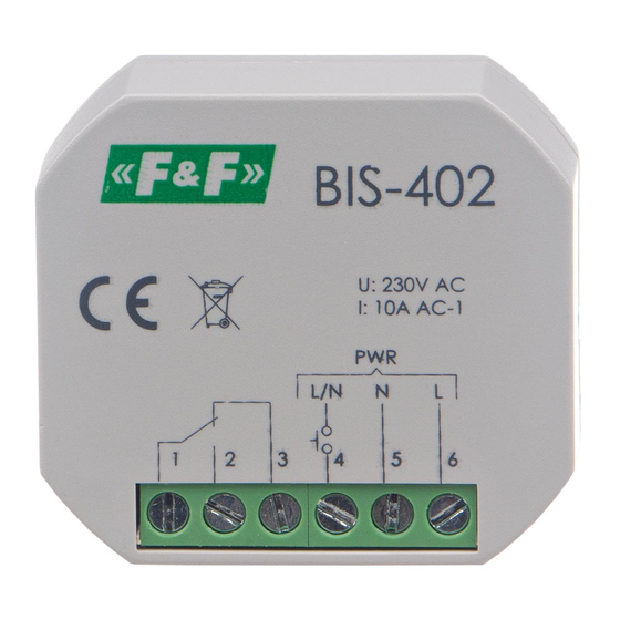
BIS-402
Bistable relay
Do not dispose of this device in the trash along with other waste!
According to the Law on Waste, electro coming from households free of charge and can
give any amount to up to that end point of collec� on, as well as to store the occasion of
the purchase of new equipment (in accordance with the principle of old-for-new, regard-
less of brand). Electro thrown in the trash or abandoned in nature, pose a threat to the
environment and human health.
Purpose
Electronic bistable pulse relay BIS-402 allows switching on or off
the lighting or other device from several different points by pa-
rallel connected, momentary (bell) control switches.
Functioning
The receiver is switched on after a current pulse caused by pres-
sing any momentary (bell) button connected to the relay. After
the next pulse, the receiver will be switched off.
The relay does not have a „memory" of the contact position,
which means in the event of a power failure and its subsequ-
ent return, the relay contact will be set to „off". This prevents
the controlled receivers from being switched on automatically
without supervision after a prolonged power failure.
F&F Filipowski L.P.
Konstantynowska 79/81, 95-200 Pabianice, POLAND
phone/fax (+48 42) 215 23 83 / (+48 42) 227 09 71
www.fif.com.pl; e-mail: biuro@fif.com.pl
- 1 -
Advertisement

Related Manuals for F&F BIS-402


Summary of Contents for F&F BIS-402
- Page 1 Electro thrown in the trash or abandoned in nature, pose a threat to the environment and human health. Purpose Electronic bistable pulse relay BIS-402 allows switching on or off the lighting or other device from several different points by pa- rallel connected, momentary (bell) control switches.
- Page 2 4. Connect parallel connected momentary switches to the termi- nal 4 and phase wire L or N. 5. Connect the receiver’s power to the terminal 1. 6. Connect the receiver to the terminal 2 and the neutral wire N. BIS-402 cannot work with backlit buttons. - 2 -...
- Page 3 Wiring diagram COM common contact NO contact NC contact triggering input 165÷265 V AC power supply of relay Technical data power supply 165÷265 V AC contact separated 1×NO/NC maximum load current (AC-1) 10 A control pulse current 1 mA triggered with L or N level activation delay 0.1÷0.2 s power consumption...
- Page 4 Technical data (cont.) mounting in flush mounted box ø60 ingress protection IP20 Power table tungsten halogen fluorescent energy-saving 1500 W 1000 W 500 W 300 W 300 W The above data are indicative and will heavily depend on the design of a specific receiver (that is especially important for LED bulbs, energy-saving lamps, electronic transformers and pulse power supply units), switching frequency and operating conditions.
Need help?
Do you have a question about the BIS-402 and is the answer not in the manual?
Questions and answers