
Subscribe to Our Youtube Channel
Related Manuals for Uni-Mig PLASMA CUT40


Summary of Contents for Uni-Mig PLASMA CUT40
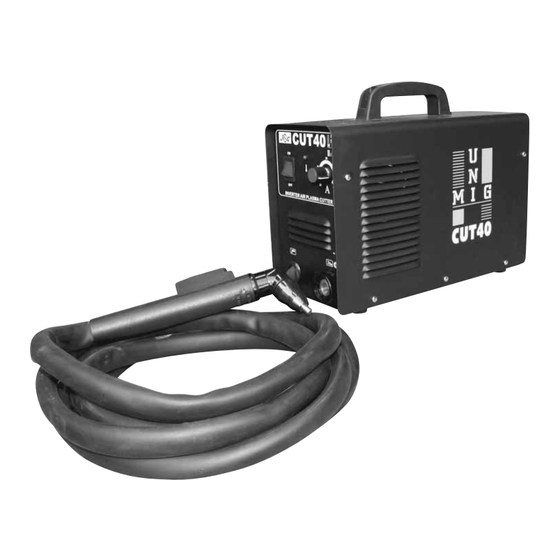
- Page 1 UNI FLAME AUTOLIFT PLASMA CUT40 Inverter Air Plasma Manual MILD STEEL 240 Volt Plasma CUT MAXIMUM CUTTING CAPACITY 10MM...
-
Page 2: Table Of Contents
YEARS Warranty Machine Model Description Part Number Plasma Cut 40 KUPJR40 CONTENTS PAGE No: Safety General Description Curcuit Diagram Main Parameter Installation & Operation Regulator Installation Operation Spare Parts List - Machine Spare Parts List - Torch Maintenance Trouble Shooting EC DECLARATION OF CONFORMITY Hereby we declare that our machines for industrial and professional use as stated below:... -
Page 3: Safety
SAFETY Welding and cutting equipment can be dangerous to both the operator and people in or near the surrounding working area, if the equipment is not correctly operated. Equipment must only be used under the strict and comprehensive observance of all relevant safety regulations. Please read and understand this instruction manual carefully before the installation and use/operation of this equipment. -
Page 4: General Description
2. GENERAL DESCRIPTION & SAFEGUARDS The plasma cutting unit generates constant current and has been designed to cut metals. The cutting process is carried out through the melting of the metal caused by high temperature created by the electric arc between the torch electrode and the base metal. -
Page 5: Curcuit Diagram
3. CIRCUIT DIAGRAM Single Phase Input... -
Page 6: Main Parameter
MAIN PARAMETER Machine Model Description Part Number Plasma Cut 40 KUPJR40 Tecnical Specification Input voltage (V) 240V AC ±10% Input Frequency (Hz) 50/60 Input capacitance (KVA) No-load voltage (V) Current range (A) 20-40 Output cutting voltage (V) Rated duty cycle (%) 30% @ 40AMPs / 100% @ 25AMPS Efficiency (%) Power factor... -
Page 7: Installation & Operation
INSTALLATION & OPERATION INSTALLATION AND OPERATION In order for the unit to function correctly, it must be installed properly. Follow the procedure given below for correct installation: Read the safety rules given in this manual carefully. Check on receiving the unit that there are no defective parts or parts damaged during transportation. -
Page 8: Regulator Installation
CAUTION: Do not point the torch jet at foreign bodies CAUTION: Avoid unnecessary lighting of the pilot arc to prevent excessive consumption of the electrode and nozzle. CAUTION: During cutting the speed of the torch movement should be in accordance with the thick- ness of the piece to be cut. -
Page 9: Operation
OPERATION Of the torch CAUTION: Before inspecting or changing the parts of the torch, disconnect the power supply to the unit. Special tools are not required to replace torch parts. Simply unscrew the shield cup and all the components of the torch can easily be replaced. CAUTION: Unscrew the sheild cup only after the cooling air flow has stooped (the in observance of this precaution may damage the torch body) -
Page 10: Spare Parts List - Machine
Spare Parts Description WGA Part No. J02042 Front panel J03235 Cover J24005 Handle C16001 Knob CX0031 35/50 Panel socket female B01005 Top PCB C08608 Input cable J20003, J20004 Heat sink B03012 Bottom PCB C16001 Main switch B15002 J24009 Rubber foot B02002 Center PCB... -
Page 11: Spare Parts List - Torch
Front end consumables Spare Parts WGA Part No. Description 07035 70° Torch head 07103 Handgrip complete with microswitch 52519/D Electrode - Hf 60050 Gas Distributor 51290 Tip - 35 Amp. Air 52523/D Electrode - Hf (long life) 60051 Gas Distributor (long life) 51288 Tip - Standoff (long life) 51289... -
Page 12: Maintenance
MAINTENANCE WARNING: Exposure to extremely dusty, damp, or corrosive air is damaging to the welding machine. In order to prevent any possible failure or fault of this welding equipment, clean the dust at regular intervals with clean and dry compressed air of required pressure.
Need help?
Do you have a question about the PLASMA CUT40 and is the answer not in the manual?
Questions and answers