
Subscribe to Our Youtube Channel
Related Manuals for Uni-Mig KUMJRRW175MIG


Summary of Contents for Uni-Mig KUMJRRW175MIG
- Page 1 OPERATING MANUAL KUMJRRW175MIG KUMJRRW200MIG YEARS Warranty (Power Source) Please read and understand this instruction manual carefully before the installation and operation of this equipment. © Welding Guns Of Australia PTY LTD 2013...
- Page 2 Secondly they provide a customer support service that is second to none, thus ensuring our customers have confidence that they will be well satisfied both now and in the future. UNI-MIG welders are manufactured and compliant with - AS/NZ60974.1 2006 - AS60974-6:2006 guaranteeing you electrical safety and performance. WARRANTY •...
- Page 3 CONTENTS PAGE Warranty Technical Data, Product Information Safety - Cautions Machine Layout Pictogram Installation & Operation for MMA (stick) Welding MMA (Stick) Welding Information 10-11 Installation & Operation for MIG Welding with Gas 12-13 Wire Feed Drive Roller Selection Wire Installation Set up Guide Installation &...
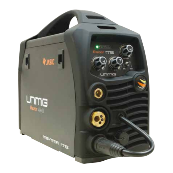
- Page 4 Designed and built to our specification. Certified to - AS/NZ60974.1 Product Code: KUMJRRW175MIG Package includes: MIG175 Welding Machine, SB25 MIG Torch x 3m, Earth Lead & Arc Lead 25mm x 4m, Argon Regulator, Gas hose with quick connect fitting.
- Page 5 DC MIG/MMA INVERTER MIG/STICK - 200Amp DC inverter welder Welds: Steels, Stainless, Cast Iron, Bronze & Aluminium KUMJRRW200MIG Features • Latest IGBT inverter technology • MIG/MAG with Gas and Gasless wire function • Excellent Mig welding with CO2 gas & mixed gases •...
- Page 6 SAFETY Welding and cutting equipment can be dangerous to both the operator and people in or near the surrounding working area, if the equipment is not correctly operated. Equipment must only be used under the strict and comprehensive observance of all relevant safety regulations. Read and understand this instruction manual carefully before the installation and operation of this equipment.
- Page 7 Fire hazard. Welding on closed containers, such as tanks,drums, or pipes, can cause them to explode. Flying sparks from the welding arc, hot work piece, and hot equipment can cause fires and burns. Accidental contact of electrode to metal objects can cause sparks, explosion, overheating, or fire. Check and be sure the area is safe before doing any welding. • The welding sparks & spatter may cause fire, therefore remove any flammable materials well away from the working area. Cover flammable materials and containers with approved covers if unable to be moved from the welding area. •...
- Page 8 CAUTION 1. Working Environment. 1.1 The environment in which this welding equipment is installed must be free of grinding dust, corrosive chemicals, flammable gas or materials etc, and at no more than maximum of 80% humidity. 1.2 When using the machine outdoors protect the machine from direct sun light, rain water and snow etc; the temperature of working environment should be maintained within -10°C to +40°C. 1.3 Keep this equipment 30cm distant from the wall. 1.4 Ensure the working environment is well ventilated.
- Page 9 FRONT PANEL LAYOUT 1. Mains Power LED 2. VRD LED 3. Thermal Overload LED 4. Wire Feed Adjustment Knob (MIG/MAG) 5. Voltage Adjustment Knob (MIG/MAG) 6. MIG/MMA Selector Switch 7. Amperage Adjustment Knob (MMA) 8. “-” Output terminal 9. Euro Mig Torch Connector (MIG/MAG) 10.
- Page 10 Installation set up for MMA (Stick) Welding with RAZOR 175-200 MIG (1) Turn the power source on and select the MMA function with the MIG/MMA selector switch. (2) Connection of Output Cables Two sockets are available on this welding machine. For MMA welding the electrode holder is shown be connected to the negative socket, while the earth lead (work piece) is connected to the positive socket, this is known as DC- polarity.
- Page 11 MMA (Manual Metal Arc) Welding One of the most common types of arc welding is manual metal arc welding (MMA) or stick welding. An electric cur- rent is used to strike an arc between the base material and a consumable electrode rod or ‘stick’. The electrode rod is made of a material that is compatible with the base material being welded and is covered with a flux that gives off gaseous vapours that serve as a shielding gas and providing a layer of slag, both of which protect the weld area from atmospheric contamination. The electrode core itself acts as filler material the residue from the flux that forms a slag covering over the weld metal must be chipped away after welding.
- Page 12 MMA (Stick) Welding Fundamentals Electrode Selection As a general rule, the selection of an electrode is straight forward,in that it is only a matter of selecting an electrode of similar composition to the parent metal. However, for some metals there is a choice of several electrodes, each of which has particular properties to suit specific classes of work. It is recommend to con- sult your welding supplier for the correct selection of electrode.
- Page 13 Installation set up for MIG with Gas for RAZOR 175-200 MIG (1) Select the MIG function with the MIG/MMA selector switch. (2) Select Standard using the Standard/Spool Gun selector switch. (3) Plug the welding torch into the Euro Mig torch connection socket on the front panel, and tighten it. When connecting the torch be sure to tighten the connection.
- Page 14 Continued set up for MIG with Gas for RAZOR 175-200 MIG (9) Align the wire into the groove of the drive roller and close down the top roller making sure the wire is in the groove of the bottom drive roller, lock the pressure arm into place. (10) Apply a medium amount of pressure to the drive roller.
- Page 15 Wire Feed Roller Selection The importance of smooth consistent wire feeding during MIG welding cannot be emphasized enough. Simply put the smoother the wire feed then the better the welding will be. Feed rollers or drive rollers are used to feed the wire mechanically along the length of the welding gun. Feed rollers are designed to be used for certain types of welding wire and they have different types of grooves machined in them to accommodate the different types of wire.
- Page 16 Wire Installation and Set Up Guide Again the importance of smooth consistent wire feeding during MIG welding cannot be emphasized enough. The correct installation of the wire spool and the wire into the wire feed unit is critical to achieving an even and consistent wire feed.
- Page 17 Installation set up for MIG with Gasless wire for RAZOR 175-200 MIG (1) Switch on the machine, select the MIG function with the MIG/MMA selector switch. (2) Select Standard using the Standard/Spool Gun selector switch. (3) Plug the welding torch into the Euro Mig torch connection socket on the front panel, and tighten it. When connecting the torch be sure to tighten the connection.
- Page 18 Continued set up for MIG with Gasless wire for RAZOR 175-200 MIG (8) Carefully feed the wire over the drive roller into the outlet guide tube, feed through about 150mm into the torch receptacle. Check that the correct drive roller is being used. (9) Align the wire into the groove of the drive roller and close down the top roller making sure the wire is in the groove of the bottom drive roller, lock the pressure arm into place.
- Page 19 Mig Torch Liner Installation (1) Lay the torch out straight on the ground and remove the front end parts (2) Remove the liner retaining nut. (3) Carefully pull the liner out of the torch cable assembly (4) Select the correct new liner and carefully unravel avoiding putting any kinks in the liner, if you kink the liner it will make it no good and will require replacement.
- Page 20 Torch & Wire Feed Set Up for Aluminium Wire (1) Lay the torch out straight on the ground and remove the front end parts (2) Remove the liner retaining nut. (3) Carefully pull the liner out of the torch cable assembly (4) Select a PA or liner, carefully and slowly feed the liner in short forward movements down the cable assembly all the way through and out the torch neck end.
- Page 21 Continued Torch & Wire Feed Set Up for Aluminium Wire (10) Loosen off the inlet guide tube retaining screw (11) Remove the inlet guide tube from the front end machine euro connector using long nose pliers. (12) Carefully feed the extended PA liner section into the inlet guide tube hole of the machine euro connector (13) Feed the extended PA liner all the way up and over the drive roller (14) Tighten the torch euro connection to the machine euro connector...
- Page 22 Installation set up of the Spool Gun for RAZOR 175-200 MIG (1) Switch on the machine, select the MIG function with the MIG/MMA selector switch. (2) Select Spool Gun using the Standard/Spool Gun selector switch. (3) Connect the Spool Gun to the Euro MIG torch connection socket on the front panel, and tighten it. Connect the Spool Gun control cable to the receptacle and tighten it.
- Page 23 Continued set up of the Spool Gun for RAZOR 175-200 MIG Carefully feed the wire through the red guide tube into meet the drive roller. Push down the tension arm adjustment lever to release the drive roll pressure allowing the wire to be guided through the drive rollers into the gun neck.
- Page 24 MIG (Metal Inert Gas) Welding Definition of MIG Welding MIG (metal inert gas) welding also known as GMAW (gas metal arc welding) or MAG (metal active gas welding), is a semi-automatic or automatic arc welding process in which a continuous and consumable wire electrode and a shielding gas are fed through a weld- ing gun.
- Page 25 MIG (Metal Inert Gas) Welding Short Circuit Transfer - Short circuit transfer is the most common used method whereby the wire electrode is fed continuously down the welding torch through to and exiting the contact tip. The wire touches the work piece and causes a short circuit the wire heats up and begins to form a molten bead, the bead separates from the end of the wire and forms a droplet that is transferred into the weld pool.
- Page 26 Basic MIG Welding Good weld quality and weld profile depends on gun angle, direction of travel, electrode extension (stick out), travel speed, thickness of base metal, wire feed speed (amperage) and arc voltage. To follow are some basic guides to assist with your setup. Gun Position - Travel Direction, Work Angle Gun position or technique usually refers to how the wire is directed at the base metal, the angle and travel direction chosen.
- Page 27 Travel Angle - Travel angle is the right to left angle relative to the direction of welding. A travel angle of 5°- 15° is ideal and produces a good level of control over the weld pool. A travel angle greater that 20° will give an unstable arc condition with poor weld metal transfer, less penetration, high levels of spatter, poor gas shield and poor quality finished weld.
- Page 28 Travel Speed - Travel speed is the rate that the gun is moved along the weld joint and is usually measured in mm per minute. Travel speeds can vary depending on conditions and the welders skill and is limited to the welders ability to control the weld pool. Push technique allows faster travel speeds than Drag technique. Gas flow must also correspond with the travel speed, increas- ing with faster travel speed and decreasing with slower speed.
- Page 29 Wire types and sizes - Use the correct wire type for the base metal being welded. Use stainless steel wire for stainless steel, aluminium wires for aluminium and steel wires for steel. Use a smaller diameter wire for thin base metals. For thicker materials use a larger wire diameter and larger machine, check the recommended welding capability of you machine.
- Page 30 Suregrip Series SB24 MIG TORCH 250A AIR COOLED MIG WELDING TORCH Rating:250A CO² 220A mixed gas EN60974-7 @ 60% duty cycle. 0.8 to 1.2mm wires Wear parts next page Wear parts next page Torch Model Description Part Number 3 Mt 4 Mt 5 Mt SB Suregrip Ergo Torch Package...
- Page 31 Suregrip Series SB24 MIG TORCH Front end consumables SB24 Contact Tips Part Number Description PCT0009-06 Contact Tip Steel (0.6mm) QTY10 PCT0009-08 Contact Tip Steel (0.8mm) QTY10 PCT0009-09 Contact Tip Steel (0.9mm) QTY10 PCT0009-10 Contact Tip Steel (1.0mm) QTY10 PCT0009-12 Contact Tip Steel (1.2mm) QTY10 28.0 QTY10...
- Page 32 Suregrip Series SB25 MIG TORCH 250A AIR COOLED MIG WELDING TORCH Rating:230A CO² 200A mixed gas EN60974-7 @ 60% duty cycle. 0.8 to 1.2mm wires Wear parts next page Wear parts next page Torch Model Description Part Number 3 Mt 4 Mt 5 Mt SB25 Suregrip Ergo Torch Package...
- Page 33 Suregrip Series SB25 MIG TORCH Front end consumables SB25 Contact Tips Part Number Description PCT0009-06 Contact Tip Steel (0.6mm) QTY10 QTY10 PCT0009-08 Contact Tip Steel (0.8mm) PCT0009-09 Contact Tip Steel (0.9mm) QTY10 PCT0009-10 Contact Tip Steel (1.0mm) QTY10 PCT0009-12 Contact Tip Steel (1.2mm) QTY10 PCT0009-16 Contact Tip Steel (1.6mm)
- Page 34 SPG135 AMP SPOOL GUN L135YE SPOOL GUN Duty Cycle 30% @ 135Amp Description Part Number XcelArc Spool Gun SPG135 x 6m SPG135 Spare Parts Part Number Description Part Number Description LGJ2003 Trigger LGX2018 LMH2001 Handle LGX2019U DriveRoll U Groove 0.8-0.9mm LMT2001 Spool Cover Total Assembly LZ3603...
- Page 35 SPG135 AMP SPOOL GUN Duty Cycle 30% @ 135Amp Front end consumables SPG135 Contact Tips Part Number Description PCT0008-06 Contact Tip Steel (0.6mm) PCT0008-08 Contact Tip Steel (0.8mm) PCT0008-09 Contact Tip Steel (0.9mm) PCT0008-10 Contact Tip Steel (1.0mm) PCTAL0008-09 Contact Tip Aluminium (0.9mm) 25.0 PCTAL0008-10 Contact Tip Aluminium (1.0mm)
- Page 36 SPG200II AMP SPOOL GUN Duty Cycle 35% @ 200Amp Torch Model Description Part Number XcelArc Spool Gun x 6m SPG200II Spare Parts Part Number Description Part Number Description LMZ2017 Speed Adjusting Knob LMZ2014 Potentiometer LMH2114 Open/Close Button LMZ2015 Push Roll LMH2111 Left-Gun Case LMK2001...
- Page 37 SPG200II AMP SPOOL GUN Front end consumables SPG200II Contact Tips Part Number Description PCTH24 Contact Tip Holder PCT0009-06 Contact Tip Steel (0.6mm) PCT0009-08 Contact Tip Steel (0.8mm) PCT0009-09 Contact Tip Steel (0.9mm) 28.0 26.0 PCT0009-10 Contact Tip Steel (1.0mm) PCT0009-12 Contact Tip Steel (1.2mm) PCT0009-16 Contact Tip Steel (1.6mm)
- Page 38 MIG WELDING TROUBLE SHOOTING The following chart addresses some of the common problems of MIG welding. In all cases of equipment malfunction, the manu- facturer’s recommendations should be strictly adhered to and followed. 1: Excessive Spatter Possible Reason Suggested Remedy Wire feed speed set too high Select lower wire feed speed Voltage too high Select a lower voltage setting Wrong polarity set...
- Page 39 MIG WIRE FEED TROUBLE SHOOTING The following chart addresses some of the common WIRE FEED problems during MIG welding. In all cases of equipment malfunction, the manufacturer’s recommendations should be strictly adhered to and followed. 1: No wire feed Possible Reason Suggested Remedy Wrong mode selected Check that the TIG/MMA/MIG selector switch set to MIG position Wrong torch selector switch Check that the STANDARD/SPOOLGUN selector switch is set to STANDARD position for MIG welding and SPOOLGUN when using the Spoolgun...
- Page 40 MMA (Stick) WELDING TROUBLE SHOOTING The following chart addresses some of the common problems of MMA welding. In all cases of equipment malfunction, the manufacturer’s recommendations should be strictly adhered to and followed. 1: No arc Possible Reason Suggested Remedy Incomplete welding circuit Check earth lead is connected. Check all cable connections. Wrong mode selected Check the MMA selector switch is selected No power supply...
- Page 41 ATTENTION! - CHECK FOR GAS LEAKS At initial set up and at regular intervals we recommend to check for gas leakage. Recommended procedure is as follows: 1. Connect the regulator and gas hose assembly and tighten all connectors and clamps. 2.
- Page 42 Spare Parts Identification - MIG165 Description Part Number Description Part Number Carry handle 10043478 Power Input Cable 10043418 Front cover 10043403 Gas hose Wire feed potentiometer 10037793 Gas Solenoid 10040667 MMA/MIG toggle switch 10004968 Rectifier bridge 10039915 MIG voltage potentiometer 10037793 Wire Feeder Motor 10042965 MMA amperage potentiometer...
- Page 43 Spare Parts Identification - MIG200 Description Part Number Description Part Number Carry handle 10043478 Power Input Cable 10043418 Front cover 10043403 Gas hose Wire feed potentiometer 10037793 Gas Solenoid 10040667 MMA/MIG toggle switch 10004968 Rectifier bridge 10039915 MIG voltage potentiometer 10037793 Wire Feeder Motor 10042965 MMA amperage potentiometer...
- Page 44 Email: sales@unimig.com.au / Web: www.unimig.com.au ABN: 14 001 804 422 Welding Guns Of Australia Pty Ltd (‘Us’, ‘We’) warrants that the following products under UNI-MIG, UNI-TIG, UNI-PLAS, UNI-FLAME, TECNA, T&R, HIT-8SS & ROTA, supplied by Us and purchased by you from an Authorised UNI-MIG, UNI-TIG, UNI-PLAS, UNI-FLAME, TECNA, T&R, HIT-8SS &...
- Page 45 WARRANTY / RETURNS / EXCHANGES We understand that sometimes you may need to return a product you have purchased from Welding Guns Of Australia PTY LTD Authorised Dealer Network, to assist you, we have set out below the Welding Guns Of Australia PTY LTD Returns Policy that you should know.
- Page 46 Failure or any breakage caused by overload, dropping or abusive treatment or use by the customer • Repair, modifications or other work carried out on the product other than by an Authorised UNI-MIG, UNI-TIG, UNI-PLAS, UNI-FLAME, TECNA, T&R, HIT-8SS & ROTA Service Dealer...
- Page 47 Input Cord, Inter-connecting Cord, Triggering Cable. This Warranty does not cover products purchased: • From a non-authorised UNI-MIG, UNI-TIG, UNI-PLAS, UNI-FLAME, TECNA,T&R, HIT-8SS & ROTA Dealer (such as purchases from unauthorised retailers and purchases over the Internet from unauthorised local/international sellers or sites such as EBay) •...
- Page 48 © Welding Guns Of Australia PTY LTD 2013 Welding Guns Of Australia Pty Ltd ABN: 14 001 804 422 PO Box 3033, Lansvale NSW 2166, AUSTRALIA 112 Christina Rd, Villawood, NSW 2163 Phone: (02) 9780 4200 Fax: (02) 9780 4244 Email: sales@unimig.com.au / Web: www.unimig.com.au...
Need help?
Do you have a question about the KUMJRRW175MIG and is the answer not in the manual?
Questions and answers