Table of Contents
Advertisement
Quick Links
Advertisement
Table of Contents

Related Manuals for Iwata CM24-HHYBRID AC-i4 PRO


Summary of Contents for Iwata CM24-HHYBRID AC-i4 PRO
- Page 1 AIR COOLER & AIR CONDITIONER (DUAL FUNCTION)
-
Page 2: Table Of Contents
CONTENT Ⅰ Product Introduction -----------------------------------------------------------------------1 Ⅱ Main Specification ------------------------------------------------------------------------2 Ⅲ Applications --------- --------- ------------------------------------------------------------2 Ⅳ Product usage conditions -------------------------------------------------------------2 Ⅴ Identification of parts -------------------------------------------------------------3 Ⅵ Circuit Wiring Diagram -----------------------------------------------------------------4 Ⅶ Operating & Installation Instructions ----------------------------------------------- 5 Ⅷ Maintenance Instructions -----------------------------------------------------------8 Ⅸ... -
Page 3: Ⅰ Product Introduction
REMOVE ALL PACKING MATERIALS FROM THIS PRODUCT BEFORE USING IT. THIS APPLIANCE MUST BE INSTALLED ON A FLAT AND LEVEL SURFACE. Please read this manual carefully. It is advisable to keep this instruction manual in a safe place for future reference. Ⅰ... -
Page 4: Ⅱ Main Specification
Ⅱ Main Specifications Model No. CM24-HYBRiD AC-i4 PRO Airflow (m³) 9000 Cooling Capacity(BTU/H) 9000 Refrigerant R410A Input Power(W) 1180 Voltage (V) 230V~ Rated Current (A) Noise (dB) ≤60 Air Outlet Size (MM) 610*630 Fan Speeds Water Tank(L) Dimension(MM) 790*520*1350 Gross Weight (KG) Applicable Area( ㎡... -
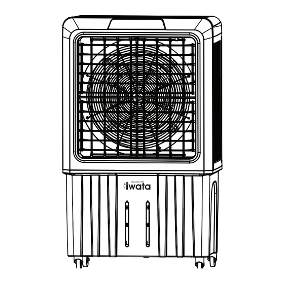
Page 5: Ⅴ Identification Of Parts
Ⅴ Identification Of Parts Piped water inlet #1 Piped water inlet #2 Wheel Wheel Drain Drain outlet #1 outlet #2 Exhaust fan outlet Filter Mesh Evaporative Cooling pads Water inlet (for hose) Water tank Ⅵ Circuit Wiring Diagram Wheels - 3 -... - Page 6 Ⅴ Structure Diagram ⅤI Circuit Wiring Diagram Control panel Water lever sensor Swing motor Water pump Yellow / LOW Fan Motor Blue / MID Black / HI COMPRESSOR • • • • • • • • • • • • •...
-
Page 7: Vii Operating & Installation Instructions
VII Operating & Installation Instructions Step #1: Install the 4 wheels at the bottom of the water tank by gently slanting it with the help of an assistant on a flat and level surface using a screw drivers and the screws supplied. WARNING: . - Page 8 Step #2: Place the unit upright and wait for at least 3 hours before operating the unit (to allow the oil in the compressor to settle down) Step #3: Add water by connecting water hose to the float valve (located on the 2 sides of the water tank) or manually pour water manually from the rear side of the water tank Cautions: 1.
- Page 9 7 .AIR COOLER button, the water pump will be activated and the unit functions Press AIR COOLER AIR COOLER mode. Remote control instruction Press this button once, the unit will activate AIR-CON mode If you press the button again, it will turn the unit OFF. Press this button,the fan will work in a cycle of low,medium and high speed and will change speed every 20 seconds.
-
Page 10: Ⅷ Maintenance Instructions
LEARN MORE FOR AFTER SALES SERVICE COLENT MARKETING PHILIPPINES, INC. (CMPI) Berton's Place #46 Sta. Rosa St. Barangay Manresa Quezon City, Philippines. Tel Nos. 8442-3856; 8442-3866; 3448-7674; 3412-6155; 3413-9503; 8282-5049; 8282-5098 Email: iwata@colentco.com , iwata2@colentco.com , iwata3@colentco.com, sales_mktg@colentco.com Website: www.colentco.com...
Need help?
Do you have a question about the CM24-HHYBRID AC-i4 PRO and is the answer not in the manual?
Questions and answers