Advertisement
Quick Links
DM
Series C
1
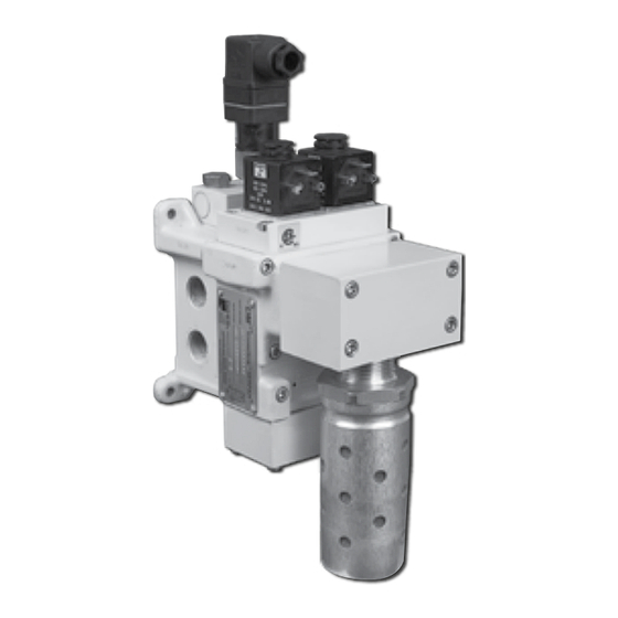
Double Valves with Dynamic Monitoring Basic Size 2, 4 & 8
Thank You!
The valve exhausts downstream air if asynchronous movement of valve elements occurs during actuation or de-actuation, resulting in
a residual outlet pressure of less than 1% of supply. If the abnormality clears itself, the valve will return to the ready-to-run state; there
is no memory of the abnormal behavior, as in the ROSS DM
following lockout. With care in its installation and maintenance you can expect it to have a long and economical service life. Before
you install this valve, read the information in this folder completely, and save it for future reference.
IMPORTANT APPLICATION NOTE: Because its characteristics are for Category 4 applications this valve is not for use
in press clutch/brake applications. ROSS produces the DM
flow, exhaust and lockout characteristics for press clutch/brake applications.
Please read and make sure you understand all installation instructions before proceeding with the installation.
If you have any questions about installation or servicing your valve, please contact ROSS or your authorized ROSS distributor, see contact information
Pneumatic equipment should be installed only by persons trained and experienced in such installation.
Air Lines: Before installing this valve in a new or existing system, the air
lines must be blown clean of all contaminants.
It is recommended that an air filter be installed in the inlet line close to the valve.
Valve Inlet (Port 1): Be sure that the supply line is of adequate size and
does not restrict the air supply because of a crimp in the line, a sharp bend,
or a clogged filter element. The air supply must not only provide sufficient
pressure (see Standard Specifications, page 3), but must also provide an
adequate flow of air on demand.
Valve Outlet (Port 2): For faster pressurizing and exhausting of the
mechanism being operated by the valve, locate the valve as close as
possible to the mechanism. The lines must be of adequate size and be free
of crimps and sharp bends.
Valve Exhaust (Port 3): Do not restrict the air flow from the exhaust port as
this can adversely affect the operation of the valve. The valves are factory
equipped with a properly sized silencer. ROSS silencers reduce impact
noise by as much as 25 dB, with minimum back pressure.
Electrical Supply: DM
Series C valves get electrical power through plug-
1
in connectors. The electrical supply must correspond to the voltage and
frequency ratings of the solenoids; otherwise the solenoids are subject to
early failure. If power is supplied by a transformer, the power supply must
be capable of handling the maximum power. See Valve Specifications on
page 3 for information on maximum power.
Operating Pressures and Temperatures: Allowable ranges for pressure and
temperatures are given in the Standard Specifications on page 3. Exceeding
these values can adversely affect performance and shorten valve life.
Pipe Installation: To install pipe in ports, engage pipe one turn, apply pipe
thread sealant (tape not recommended), and tighten pipe. This procedure
will prevent sealant from entering and contaminating the valve. To install
pipe with parallel threads (e.g., SAE, ISO 228-I, etc.) do not use sealant.
Test: After installation or repair and prior to normal use, the valve must be
tested for proper functioning. Observe normal equipment operation safety
precautions such as lockout procedures during these tests to avoid personal
injury or damage to equipment.
DM
Series C Testing Procedure:
1
NOTE: After DM
Series C valves do "lockout" they may not stay in the
1
"lockout condition" as do the DM
function. The valves that include memory functions, once "locked-out",
must be reset by a dedicated reset function in order to be operated again.
ROSS CONTROLS
®
Control Reliable
You have purchased a premium-quality ROSS
Control Reliable double valve with Dynamic Monitoring for Category 3 and 4 applications. Monitoring
and air flow control functions are integrated into two identical valve elements for CAT 4 applications.
Series E and DM
2®
2 ®
VALVE INSTALLATION
Additional technical documentation is available for download at www.rosscontrols.com.
listed at the back of this document, or visit www.rosscontrols.com to find your distributor.
Series C valves that remember abnormal
2®
pneumatic valve. It is a high quality DM
®
Series C products that require an intentional reset
2®
Series D and a number of other double valve configurations with
DM
Series C valves will operate again as soon as the fault condition has
1
cleared. Removing electrical power to both pilot solenoids may clear the
lockout condition if the situation that caused the valve internals to not operate
simultaneously is no longer in effect. This is referred to as "automatic reset."
This may result in momentary lockout going undetected during machine
operation without the use of the optional status indicator.
A) Electrically energize both pilot solenoids simultaneously. The valve
should supply pressure from inlet port (1) to outlet port (2). There should
be no flow to the exhaust port (3) at this time.
B) De-energize one of the pilot solenoids. The valve should go into a lockout
condition such that any downstream pressure in the outlet port (2) will be
exhausted to atmosphere through exhaust port (3). There should also be
a small, but audible, flow of air out the exhaust port (3) as long as the valve
remains in the lockout condition.
C) Re-energize the pilot solenoid that was de-energized in step B above.
The valve must remain in the lockout condition.
D) De-energize both pilot solenoids and the DM
return to the "ready-to-run" condition. There should be no pressure present
at outlet port (2) and there should no longer be any audible flow of air to
exhaust port (3).
E) Energize both pilots simultaneously again. As in step A above, the valve
should supply pressure from inlet port (1) to outlet port (2), there should be
no flow to the exhaust port (3).
F) De-energize the other pilot solenoid. As in step B above, the valve should
again go into a lockout condition.
G) Re-energize the pilot solenoid that was de-energized in step F above.
The valve must remain in the lockout condition.
H) De-energize both pilot solenoids and the DM
return to the "ready-to-run" condition as in step D above.
Fault Indication: The status indicator shall be used to signal the machine
controls that a lockout has occurred. The status indicator utilizes a pressure
switch. The pressure switch has 4 electrical contacts (NOTE: Contact 4 is a
ground). During normal operation the pressure switch is pressurized. A lockout
condition depressurizes the switch until the valve is ready to run (after power has
been removed from both pilot solenoids). Contacts 1 and 2 are closed when the
depressurized (normally closed) and contacts 1 and 3 are closed
switch is
when an adequate pressure signal is applied to the switch (normally open).
Series C
1
1
Series C valve should
Series C valve should again
1
www.rosscontrols.com
Advertisement

Related Manuals for Ross DM1 Series


Summary of Contents for Ross DM1 Series
- Page 1 Additional technical documentation is available for download at www.rosscontrols.com. If you have any questions about installation or servicing your valve, please contact ROSS or your authorized ROSS distributor, see contact information listed at the back of this document, or visit www.rosscontrols.com to find your distributor.
- Page 2 Repair kits are available for internal components. Valves can be aniline point between 180°F (82°C) and 220°F (104°C), and an ISO returned to ROSS Controls for repair. 32 or lighter viscosity. Electrical Contacts. In the electrical circuits associated with the Some compatible oils are listed at the right.
- Page 3 VALVE SERVICE ROSS would be happy to service this valve for you at its factory repair center. If you purchased your valve from ROSS please contact ROSS customer service, if you purchased your valve thru an authorized ROSS distributor please contact the distributor for return instructions.
- Page 4 ROSS’ obligation under this warranty is limited to repair or replacement of the product or refund of the purchase price paid solely at the discretion of ROSS and provided such product is returned to ROSS freight prepaid and upon examination by ROSS is found to be defective.
Need help?
Do you have a question about the DM1 Series and is the answer not in the manual?
Questions and answers