Tektronix VM5000 Quick Start User Manual
Automatic video measurement set
Hide thumbs
Also See for VM5000:
- Programming manual (954 pages) ,
- Instructions manual (10 pages) ,
- Quick start user manual (94 pages)
Table of Contents
Advertisement
Quick Links
A l l t e s t I n s t r u me n t s , I n c .
5 0 0 C e n t r a l A v e .
F a r mi n g d a l e , N J 0 7 7 2 7
P : ( 7 3 2 ) 9 1 9 - 3 3 3 9
F : ( 7 3 2 ) 9 1 9 - 3 3 3 2
a l l t e s t . n e t
s s a l e s @ a l l t e s t . n e t
T h e t e s t & me a s u r e me n t
e q u i p me n t y o u n e e d a t
t h e p r i c e y o u w a n t .
A l l t e s t c a r r i e s t h e w o r l d ' s l a r g e s t s e l e c t i o n o f
u s e d / r e f u r b i s h e d b e n c h t o p t e s t & me a s u r e me n t
e q u i p me n t a t 5 0 % t h e p r i c e o f n e w .
O O u r e q u i p me n t i s g u a r a n t e e d w o r k i n g , w a r r a n t i e d , a n d
a v a i l a b l e w i t h c e r t i f i e d c a l i b r a t i o n f r o m o u r i n - h o u s e s t a f f
o f t e c h n i c i a n s a n d e n g i n e e r s .
• 1 0 + f u l l t i me t e c h n i c i a n s w i t h o v e r 1 5 0 y e a r s o f
s p e c i a l i z a t i o n
• 9 0 d a y w a r r a n t y & 5 d a y r i g h t o f r e t u r n o n a l l
e q u i p me n t
• • 1 - 3 y e a r w a r r a n t i e s f o r n e w a n d
p r e mi u m- r e f u r b i s h e d e q u i p me n t
• E v e r y u n i t t e s t e d t o O E M s p e c i f i c a t i o n s
• S a t i s f a c t i o n g u a r a n t e e d
Y o u h a v e p l a n s , w e w i l l h e l p y o u a c h i e v e t h e m.
A n y p r o j e c t . A n y b u d g e t .
t
G e t a q u o t e t o d a y !
C C a l l ( 7 3 2 ) 9 1 9 - 3 3 3 9 o r e ma i l s a l e s @a l l t e s t . n e t .
Advertisement
Table of Contents

Related Manuals for Tektronix VM5000


Summary of Contents for Tektronix VM5000
- Page 1 T h e t e s t & me a s u r e me n t e q u i p me n t y o u n e e d a t t h e p r i c e y o u w a n t . A l l t e s t I n s t r u me n t s , I n c .
- Page 2 VM5000 Automatic Video Measurement Set Quick Start User Manual www.tektronix.com 071-1573-01...
- Page 3 Copyright © Tektronix, Inc. All rights reserved. Licensed software products are owned by Tektronix or its subsidiaries or suppliers, and are protected by national copyright laws and international treaty provisions. Tektronix products are covered by U.S. and foreign patents, issued and pending. Information in this publication supersedes that in all previously published material.
- Page 4 Warranty 2 Tektronix warrants that this product will be free from defects in materials and workmanship for a period of one (1) year from the date of shipment. If any such product proves defective during this warranty period, Tektronix, at its option, either will repair the defective product without charge for parts and labor, or will provide a replacement in exchange for the defective product.
-
Page 6: Table Of Contents
The VM5000 Software User Interface............ - Page 7 Displaying the Input Signal in a Vectorscope Window – Options SD/HD Only ..........Index VM5000 Quick Start User Manual...
-
Page 8: General Safety Summary
Keep Product Surfaces Clean and Dry. Provide Proper Ventilation. Refer to the manual’s installation instructions for details on installing the product so it has proper ventilation. Terms in this Manual These terms may appear in this manual: VM5000 Quick Start User Manual... - Page 9 DANGER indicates an injury hazard immediately accessible as you read the marking. WARNING indicates an injury hazard not immediately accessible as you read the marking. CAUTION indicates a hazard to property including the product. The following symbols may appear on the product: VM5000 Quick Start User Manual...
-
Page 10: Preface
Preface This manual describes the installation and basic operation of the VM5000 Automatic Video Measurement Set. For more detailed information, see the online help on your instrument and the VM5000 Automatic Video Measurement Set User Manual. Key Features The VM5000 Automatic Video Measurement Set is a high-performance automated video measurement system based on an oscilloscope platform. -
Page 11: Software Upgrades
Conventions Used in this Manual This manual describes how to operate VM5000 Options SD, HD, and VGA. Although the methods of operation are identical in all three options, there are some differences in features; most notably the available measurements. Where there are differences in configuration or application, they are identified in the text by the option to which they apply. -
Page 12: Installing Your Instrument
Carefully unpack your instrument and verify that it includes the standard accessories. VM5000 Standard Accessories Accessory Part number VM5000 Automatic Video Measurement Set Quick Start User Manual in English, and French, 071-1573-XX German, Spanish, Traditional Chinese, Simplified Chinese, or Japanese translation if a language option was ordered... - Page 13 012-0991-01 GPIB cable (6.6 ft. or 2 m) 012-0991-00 Centronics (printer) cable 012-1214-00 For the current list of accessories, upgrades, and options, including service options, available for your VM5000, visit the Tektronix Web site, www.tektronix.com. VM5000 Quick Start User Manual...
-
Page 14: Operating Requirements
CAUTION. To ensure proper cooling, keep the bottom and sides of the instrument clear of obstructions. Powering On the Instrument Power Supply Requirements Source voltage and frequency Power consumption 100-240 V ±10%, 47-63 Hz or 115 V ±10%, < 220 watts 360-440 Hz VM5000 Quick Start User Manual... -
Page 15: Powering Off The Instrument
You can connect your instrument to a network for printing, file sharing, internet access, and other functions. Consult with your network administrator and use the standard Windows utilities to configure the instrument for your network. VM5000 Quick Start User Manual... -
Page 16: Creating An Emergency Startup Disk
Store this disk in a safe place. 1. If the TekScope software is running, select File > Minimize. 2. Select Start > Programs > Accessories > System Tools > Backup. 3. Select Emergency Repair Disk and follow the on-screen instructions. VM5000 Quick Start User Manual... -
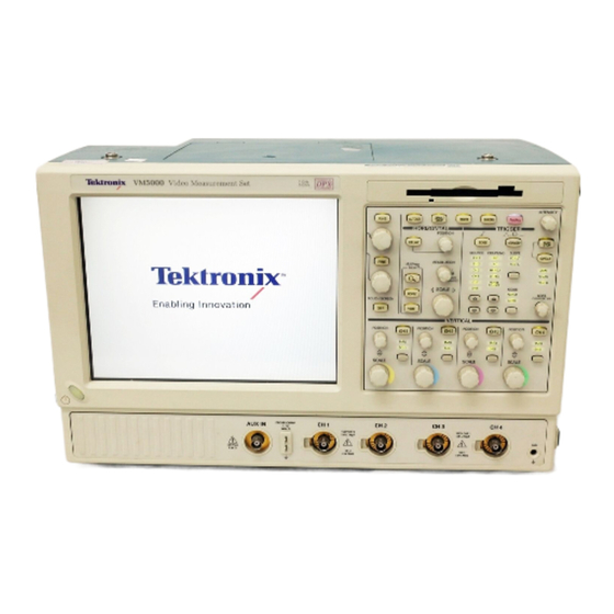
Page 17: Getting Acquainted With Your Instrument
Getting Acquainted with Your Instrument Getting Acquainted with Your Instrument Front Panel Side and Rear Panels VM5000 Quick Start User Manual... -
Page 18: Input Connection Requirements - Options Sd/Hd
Getting Acquainted with Your Instrument Input Connection Requirements – Options SD/HD Use only 75 Ω coaxial cables to connect the video device under test to the VM5000 instrument. Install the included 75 Ω terminations between the end of the coaxial cables and the instrument input channels, using the included BNC T connectors. -
Page 19: Connecting Input Signals
CH1 and CH4. The additional cabling could adversely impact frequency response and multiburst measurements. To achieve the best frequency response and multiburst measurements, the 75 Ω termination should be connected as close to the input connector as possible, as shown in the setup illustration. VM5000 Quick Start User Manual... - Page 20 Set the triggering on the instrument to channel 1 (the default trigger setting is CH4). This setup is simpler than the others mentioned in this section, but limits noise measurement on Y/G to -65 dB (30 MHz noise bandwidth). VM5000 Quick Start User Manual...
- Page 21 NOTE. Verify that the trigger channel is set to channel 4 (the default trigger channel). If the trigger setting is not set to CH4 (Configuration > Operation), you will see signal warning messages and be unable to take measurements. VM5000 Quick Start User Manual...
- Page 22 This is the preferred setup for testing PC and play-out device video. Use the RGBHV Measurement Interface Unit to connect the PC video card to the VM5000. Using the RGBHV MIU provides the most accurate measurement results. To connect the RGBHV Measurement Interface Unit: 1.
- Page 23 Getting Acquainted with Your Instrument 2. Connect the outputs (Aux, CH1–CH4) of the RGBHV Measurement Interface Unit to same inputs on the VM5000 (that is, connect the CH1 output to the CH1 input). 3. Connect the RS-232 cable between the RGBHV Measurement Interface Unit and the COM1 port on the VM5000.
- Page 24 Use this setup for testing PC and play-out device video when it is not convenient to use the RGBHV Measurement Interface Unit. To ensure accurate measurements, connect the signals to the VM5000 using the T-connectors and precision terminations on CH1-CH4. You must use 75 Ω terminations on CH1–CH3 (used for GBR) and 2.21 kΩ and 301 Ω...
- Page 25 H Sync CH 4 V Sync None V Sync signal is connected to this channel when making a V Timing or V Sync measurement. The VM5000 will prompt you for this connection change if necessary. VM5000 Quick Start User Manual...
-
Page 26: Signal Path Compensation
10 to 15 minutes. NOTE. Signal Path Compensation is the only available calibration. 4. After calibration, if the status indicator does not display Pass, recalibrate the instrument or have the instrument serviced by qualified service personnel. VM5000 Quick Start User Manual... -
Page 27: Sync Pickoff Compensation - Options Sd/Hd Only
1. Connect the sync pickoff cable to channel 1. 2. Attach the sync pickoff BNC connector to a BNC-to-minigrabbers connector (Pomona Electronics model number 3789). 3. Connect the minigrabbers to the PROBE COMP connector. 4. Push AUTOSET. VM5000 Quick Start User Manual... - Page 28 Getting Acquainted with Your Instrument 5. Check the shape of the displayed waveform to determine if the sync pickoff is compensated correctly. 6. If necessary, adjust the sync pickoff. Repeat as needed. VM5000 Quick Start User Manual...
-
Page 29: About The Matrix Test Signal
file (.vmset) that matches the format of the Matrix test signal you are using; this provides appropriate line numbers as default settings for each measurement type. See the VM5000 Automatic Video Measurement Set User Manual for a full description of the files on the signal source disks. - Page 30 Signal name 1. Half white and half black 5. Black / white / black 2. Nine colorbars 6. Full white 3. 32 steps 7. Ramp 4. Alternate white and black 8. Half white and half black VM5000 Quick Start User Manual...
-
Page 31: Starting The Vm5000 Software
Getting Acquainted with Your Instrument Starting the VM5000 Software 1. Power on the instrument. 2. Select File > Run Application > VM5000 HD and SD Video or File > Run Application > VM5000 VGA Video. Option SD/HD VM5000 Quick Start User Manual... - Page 32 Getting Acquainted with Your Instrument The instrument reduces the waveform area to the upper half of the display and opens the VM5000 application in the lower half of the display. Option SD/HD Option VGA VM5000 Quick Start User Manual...
-
Page 33: The Vm5000 Software User Interface
Hide button again. 8. App button: Select the App button in the main display to restore the VM5000 application window after hiding it. 9. Exit button: Exits the VM5000 application and returns the instrument to the default main display. -
Page 34: Configuring The Dut - Option Vga
Configuring the DUT — Option VGA To perform measurements on the DUT, you must provide an appropriate video signal to the VM5000. You accomplish this by displaying a bitmap file on the PC in which the DUT is operating. The preferred bitmap file, when taking multiple measurements, is the Matrix signal. - Page 35 5. From the View menu, select View > Full Screen Preview. This displays the bmp file in full screen mode without any borders. 6. Disconnect the output of the DUT from the monitor and connect the output of the DUT to the VM5000. VM5000 Quick Start User Manual...
-
Page 36: Setting The Input Signal Format - Options Sd/Hd
1. Select Configuration > Format. The application displays the Format view. 2. Select the appropriate video format for the signal you are measuring. 3. Select the appropriate color space for the signal you are measuring. VM5000 Quick Start User Manual... -
Page 37: Setting The Input Signal Format - Option Vga
Getting Acquainted with Your Instrument Setting the Input Signal Format – Option VGA 1. Select Configuration > Format. The application displays the Format tab view. 2. Select the appropriate resolution for the signal you are measuring. VM5000 Quick Start User Manual... - Page 38 Creating a Custom Format If you need to test a format that is not listed on the Format tab, you can create a User-Defined Format. 1. Select Configuration > Format. The application displays the Format tab view. VM5000 Quick Start User Manual...
- Page 39 User-Defined Format checkbox. 3. To add a new format, select Add. 4. Enter values for both the horizontal and vertical parameters that specify your format. Set the sync polarity. Enter a value for the refresh rate. VM5000 Quick Start User Manual...
- Page 40 Getting Acquainted with Your Instrument 5. Enter a format name and select Save to save the new format. 6. Once you have saved a new format, you can select it from the list box. VM5000 Quick Start User Manual...
-
Page 41: Selecting Measurements
Getting Acquainted with Your Instrument Selecting Measurements 1. Select Configuration > Measurements. 2. Select the desired measurements on the Measurements tab. You can select one measurement or any combination of measurements. Option SD/HD Option VGA VM5000 Quick Start User Manual... -
Page 42: Setting The Measurement Run Operations
1. Select Configuration > Operation. Option SD/HD Option VGA The instrument displays the Operation view. These settings control how the instrument sets up and acquires measurements when you select the Run button. Option SD/HD Option VGA VM5000 Quick Start User Manual... - Page 43 5. Option SD/HD: Select which instrument channel has the sync signal for triggering. If you use the wrong trigger channel, you will get a signal warning (if Signal Warnings is on). (See page 8, Connecting Input Signals.) Option SD/HD VM5000 Quick Start User Manual...
- Page 44 Option VGA When you select Multiple Lines, a report is automatically saved to a file. 7. Option VGA: If you are using the RGBHV Measurement Interface, you must select the Use MIU checkbox. Option VGA VM5000 Quick Start User Manual...
-
Page 45: Taking And Viewing Measurements
Sync Polarity setting. Because the specified polarities for the H Sync and V Sync signals vary between the timing standards, the VM5000 will prompt you to connect the H and V Sync signals to automatically determine their polarities. - Page 46 Results menu. For example, to view the Sync measurement results (Option SD/HD only), select Results > Sync. 3. If you set the run operation to Continuously, press the Stop button to stop taking measurements. VM5000 Quick Start User Manual...
-
Page 47: Using The Oscilloscope
Getting Acquainted with Your Instrument Using the Oscilloscope To use the standard oscilloscope capabilities of the VM5000 to take measurements or view features of a signal, just hide the VM5000 software. You do not have to quit the VM5000 software. -
Page 48: Troubleshooting Signal Problems
Multiburst: Invalid results for all The line number is set incorrectly, Measuring Multiburst an inappropriate input signal, or an channels incorrect configuration. Noise: Signal Change: Chan <x> The signal changed during Measuring Noise measurement. VM5000 Quick Start User Manual... - Page 49 <1–3>. Use Black-White-Black signal. Sync edge locations questionable. Make sure that the selected format is correct. H Timing: Incorrect signal in Channel Black-White-Black signal is not being Measuring H Timing <1–3>. Use Black-White-Black signal. used. VM5000 Quick Start User Manual...
- Page 50 The line number is set incorrectly, Measuring Noise inappropriate input signal, or incorrect channels. configuration. Ch-Ch Mismatch: Incorrect signal in 32–step Staircase signal not being Measuring Ch-Ch Channel <1–3>. Use the 32–step used Mismatch. Staircase signal in true color mode. VM5000 Quick Start User Manual...
- Page 51 (known) configuration and resend the most recent commands. Error occurred in configuring MIU Improper serial connection to MIU Running any or one of the CH1/CH2/CH3/CH4 measurement using connector cables are disconnected the MIU. from the VM5000. VM5000 Quick Start User Manual...
-
Page 52: Applications
Cyan 368.0 88.5 -262.4 413.4 60.2 -262.5 Green 308.2 -173.8 -219.7 375.5 -202.3 -238.4 Magenta 216.8 173.8 219.7 149.5 202.3 238.4 157.0 -88.5 262.4 111.6 -60.2 262.5 Blue 59.9 262.3 -42.7 37.9 262.5 -24.1 Black VM5000 Quick Start User Manual... - Page 53 The Tektronix Matrix pattern uses a 100% color bar signal to test the full dynamic range of each component. The color bar pattern is located at or near the top of the matrix pattern; the line numbers at which it occurs are different for each standard.
- Page 54 Applications 3. In the VM5000 application, select File > Recall Default Setup to return all settings to the factory default values. 4. Connect a signal to the inputs. (See page 8, Connecting Input Signals.) 5. Set the input signal format. (See page 25, Setting the Input Signal Format –...
-
Page 55: Simple Color Bars Measurement - Option Vga
Black The Tektronix Matrix pattern uses a 100% color bar signal to test the full dynamic range of each component. The color bar pattern is located near the top of the matrix pattern; the line numbers at which it occurs are different for each format. The following tables show the line numbers on which the different patterns in the Matrix signal are located for a 60 Hz refresh rate. - Page 56 1104 – 1289 Full White 914 – 1057 981 – 1120 1309 – 1493 Ramp 1058 –1345 1135 –1427 1514 – 1903 Half White and Half Black 1346 – 1489 1442 – 1588 1923 –2118 VM5000 Quick Start User Manual...
- Page 57 Applications The VM5000 performs the color bars measurements by first identifying the relative amplitudes of each of the three channels. Eight amplitude measurements are made on each channel, giving a total of 24 measurements in less than half a second;...
- Page 58 Applications 6. Select Configuration > Measurements. Note that Color Bars is selected by default. 7. Click the Run button. When the measurements are complete, the results screen is displayed. VM5000 Quick Start User Manual...
-
Page 59: Displaying Relative To Reference Color Bar Measurements
Displaying Relative to Reference Color Bar Measurements The VM5000 displays measurement results two ways: as measured and relative to a reference value. The relative value is calculated by subtracting the measured value from a reference value. To display measurement results relative to a reference, you must select Enable Relative Results in the Reference &... - Page 60 Applications 6. Select Configuration > Reference & Limits. 7. Check Enable Relative Result Display. By default, the VM5000 application automatically selects a reference file from a set of supplied templates, matched to the selected signal format. 8. Click the Run button.
- Page 61 Applications When the measurements are complete, the results screen is displayed. Note that the Relative and Reference tabs are now selectable. Option SD/HD Option VGA VM5000 Quick Start User Manual...
- Page 62 Applications 9. Select the Reference tab to display the Reference values used to calculate the Relative values. Option SD/HD Option VGA 10. Select the Relative tab to display the calculated Relative values. VM5000 Quick Start User Manual...
- Page 63 Applications 11. Select the % option button to display the percent difference between the measured value and the reference value. Option SD/HD Option VGA VM5000 Quick Start User Manual...
-
Page 64: Displaying Color Bar Measurements With Limit Testing
The VM5000 can display measurement results compared to a limit value and with a pass/fail indication. As with the relative measurements, the limit value is specified in a CSV-format text file. The VM5000 includes a set of template files that you can edit, so that you can specify the limit values appropriate to your application. - Page 65 4. Connect a signal to the inputs. (See page 8, Connecting Input Signals.) 5. Select the input signal format. (See page 7, Input Connection Requirements – Options SD/HD.)(See page 7, Input Connection Requirements – Option VGA.) VM5000 Quick Start User Manual...
- Page 66 6. Select Configuration > Reference & Limits. Option SD/HD Option VGA 7. Select Enable Limit Testing. By default, the VM5000 application automatically selects a limit file from a set of supplied templates, matched to the selected signal format. Option SD/HD Option VGA 8.
- Page 67 Green text indicates pass (the measured value did not exceed the limit values). Red text indicates failure (the measured value exceeded the max or min limit value). Option SD/HD Option VGA VM5000 Quick Start User Manual...
- Page 68 Applications 9. Select the Limits tab to display the Limit values used. Select either min or max to see the limits specified for the minimum and maximum acceptable values. Option SD/HD Option VGA VM5000 Quick Start User Manual...
-
Page 69: Performing Limit Testing With Two Measurements
Applications Performing Limit Testing with Two Measurements The VM5000 can perform limit testing with more than one measurement at a time. 1. Power on the instrument. 2. Select File > Run Application > VM5000 HD and SD Video or VM5000 VGA Video. - Page 70 6. Select Configuration > Reference & Limits. Option SD/HD Option VGA 7. Select Enable Limit Testing. By default, the VM5000 application automatically selects a limit file from a set of supplied templates, matched to the selected signal format. Option SD/HD...
- Page 71 8. Click the Measurements tab to select the measurement to be performed. 9. Select two measurements: Option SD/HD: Select Color Bars and Sync Option SD/HD Option VGA: Select Color Bars and Luma Levels Option VGA 10. Click the Run button. VM5000 Quick Start User Manual...
- Page 72 Applications When the measurements start, the measurement status screen appears. As the measurements are completed, Pass (or Fail) is displayed for the selected measurements. Option SD/HD Option VGA VM5000 Quick Start User Manual...
- Page 73 Applications 11. To display the results of each selected measurement, select the Results menu and select one of the selected measurements. The results screen for the selected measurement is displayed. Option SD/HD Option VGA VM5000 Quick Start User Manual...
-
Page 74: Taking Measurements Across Multiple Lines - Option Vga Only
Taking Measurements Across Multiple Lines – Option VGA Only When the VM5000 takes a measurement, where the measurement is taken (you could also say when the measurement is taken) is specified by the line number. (If you want to measure the Luma Level, you need to make sure the measurement is taken within the active video portion of the signal.) Sometimes you will need to take a measurement across more than one... - Page 75 The results file can be saved in RTF, CSV, or PDF format. To view the review the results of a Multiple Lines measurement, you must use a program other than the VM5000 application, such as Microsoft Word, Excel, or Adobe Reader.
- Page 76 Applications 5. Select Configuration > Format. 6. Select the settings for Resolution, Refresh Rate, and Timing as necessary. 7. Select Configuration > Operations. 8. Click Multi Lines in the Line Select section. VM5000 Quick Start User Manual...
- Page 77 Start Line and End Line. Use these two boxes to specify the range of lines across which you want the measurement taken. 10. To select a measurement to be taken, click the checkbox next to the measurement name. VM5000 Quick Start User Manual...
- Page 78 12. To specify the parameters of the file in which the results will be saved: Click Utilities > Generate Report. This displays the Generate Report panel. 13. To change the filename and save location, click Browse. This displays the Save dialog. VM5000 Quick Start User Manual...
- Page 79 17. If you want to save a screen capture of the signal in the report, select Configuration >Operations to display the Operations panel. Select Embed Screen Capture under Report Mode (only available if Files of type is set to Rich Text Format). VM5000 Quick Start User Manual...
- Page 80 Applications 18. Select the Run button to take the measurements. After you select Run, the VM5000 displays the results page for the first of the selected measurements and begins taking measurements. The displayed Line Number increments after each measurement is taken until the measurement for each of the specified...
-
Page 81: Displaying The Input Signal As A Picture
Applications Displaying the Input Signal as a Picture The VM5000 can display the input signal as a picture. 1. Power on the instrument. 2. Select File > Run Application > VM5000 HD and SD Video or VM5000 VGA Video. 3. Connect a signal to the inputs. (See page 8, Connecting Input Signals.) - Page 82 Applications 5. Click the maximize button to expand the picture to full screen. Option SD/HD Option VGA VM5000 Quick Start User Manual...
- Page 83 Displaying the Input Signal in a Vectorscope Window – Options SD/HD Only The VM5000 can display the input signal in a vectorscope window so that you can quickly see the color range of the signal. 1. Power on the instrument.
- Page 84 Applications 4. Select the Vectorscope button. This launches the video monitor display window. 5. Click the maximize button to expand the vectorscope display to full screen. VM5000 Quick Start User Manual...
- Page 85 Applications VM5000 Quick Start User Manual...
- Page 86 36 input signal format power supply setting, 25, 26 requirements, 3 Vectorscope display, 72 VESA test procedure Limit Testing, 53, 58 rear panel map, 6 version, 23 recovery disk, 5 viewing measurement results, 34 VM5000 Quick Start User Manual...
- Page 87 Index warning and error messages, 37 Warning Types Reported, 34 VM5000 Quick Start User Manual...
Need help?
Do you have a question about the VM5000 and is the answer not in the manual?
Questions and answers