Page 1
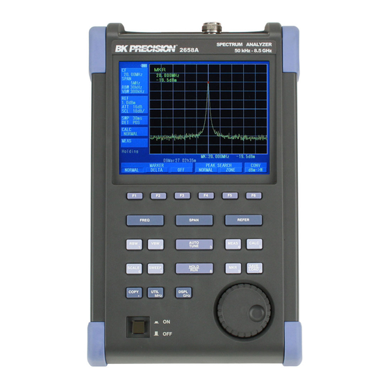
Model 2650A/2651 Series 3.3 GHz/8.5 GHz Spectrum Analyzer USER MANUAL v 092711...
Page 2
Before Using the Product · Please note the following described on the back panel. · For safe use: 1) When abnormal sound, abnormal smell or smoke is found, stop using the product and remove the battery and AC adapter. 2) Never handle this product with wet hands to prevent risks of electric shock, fire, or damage.
· Set clock function The time information is set at Japan standard time. Set the year, month, day and time when the 2650A series is used for the first time. (Refer to “24.4 Setting the clock” for the details.) · Quality assurance Warranty If the defect by our responsibility occurs within one year after delivered, it shall be repaired free of charge.
Contents OUTLINE -------------------------------------------------------------------------------------- 1 -------------------------------------------------------------------------- 1 RODUCT OUTLINES ------------------------------------------------------------------- 2 TANDARD ACCESSORIES -------------------------------------------------------------------- 2 PTIONAL ACCESSORIES ---------------------------------------------------------- 3 VERVIEW OF ALL FOUR MODELS SPECIFICATIONS -------------------------------------------------------------------------- 4 -------------------------------------------------------------------------------- 4 ERFORMANCE ------------------------------------------------------------------------------- 7 XTERNAL VIEW EXPLANATION OF PANEL ------------------------------------------------------------- 8 EXPLANATION OF SCREEN --------------------------------------------------------- 11 FUNCTION MENU ------------------------------------------------------------------------ 12 ------------------------------------------------------------------ 12 IST OF...
Page 5
VIDEO BANDWIDTH <VBW> ------------------------------------------------------ 30 12.1 MANUAL M ---------------------------------------------------------------------------- 30 12.2 AUTO M -------------------------------------------------------------------------------- 30 12.3 ALL AUTO M -------------------------------------------------------------------------- 31 SWEEP AXIS / DETECTION MODE <SWEEP> ------------------------------ 31 13.1 MANUAL M ---------------------------------------------------------------------------- 31 13.2 AUTO M -------------------------------------------------------------------------------- 31 13.3 ALL AUTO M -------------------------------------------------------------------------- 31 13.4...
Page 6
TRACKING GENERATOR MODE (2652A) ------------------------------------ 55 22.1 T.G. F ------------------------------------------------------ 55 PECIFICATION OF UNCTION 22.2 I/O C ------------------------------------------------------- 56 ESCRIPTION OF ONNECTOR 22.3 ON/OFF S T.G. F ----------------------------------------------- 56 WITCHING OF UNCTION 22.4 ------------------------------------------------------------------ 57 ORMALIZING UNCTION STORAGE/PRINT SCREEN IMAGE <COPY> -------------------------------- 58 23.1...
1. Outline 1.1 Product outlines The 2650A series are authentic spectrum analyzers in a compact and lightweight form factor providing performance and functions comparable to large-size bench type instruments. The features are as follows. 1) Compact and lightweight 1.8 kg. The dimensions are 162(W)×71(H)×265(D) mm, and the weight is only 1.8 kg including the battery, making the instrument very convenient for field use.
10) Abundant functions ● Measuring functions : Channel power, Adjacent channel power, Occupied bandwidth, Electric field strength, Magnetic field strength and Frequency measurement. ● Calculation functions : Max hold, Min hold, Averaging, Over write ● Marker measurement and peak search function ●...
Applications: 5 GHz wireless LAN, 3.5/5.8 GHz WiMAX, Maintenance of wireless base station 50 kHz to 3.3 GHz With 5 MHz to 3.3 GHz tracking generator 2652A Applications: Frequency characteristics measurement of electronic component/circuit and return loss measurement 50 kHz to 3.3 GHz...
2. Specifications 2.1 Performance Frequency section 2650A, 2652A, 2651 2658A Frequency range 50 kHz to 3.3 GHz 50 kHz to 8.5 GHz Frequency Frequency Harmonic range band order 50 k to 3.5 Base band ――― 3.3 G to 6.3 Band 1- 6.1 G to 8.5...
Page 11
Amplitude section 2650A, 2652A, 2651 2658A Reference level Setting range +10 to -60 dBm (1dB step) Accuracy within ± 0.8 dB ± 1 dot @ center frequency : 100 MHz, RBW : 3 MHz, VBW : 1 MHz, REF : -15 dBm, 23±5 °C dBm, dBV, dBmV, dBμV, dBμV/m, dBμA/m...
Page 12
Positive peak, Negative peak, Sample ( QP and AV for model 2651 only.) Function 2650A, 2652A, 2658A, 2651 common Marker measurement NORM:displays frequency (8digits max) and level (4digits max) at marker point. DELTA:displays frequency difference and level difference between two markers.
(excluding projections, protection bumper and stand) Weight approx. 1.8 kg or 4 lbs (including battery) * Refer to section 22) Tracking Generator Mode for the specifications of the tracking generator, model 2652A. 2.2 External view [Unit : mm] * B&K Precision reserves the right to make changes in design, specification and other information without prior notice.
3. Explanation of Panel 1) TFT display This is a large liquid crystal display with 640 (H) x 480 (V) dots. It simultaneously displays spectrum (10div x 10 div), various setting parameters and measured values. 2) Function key (F1 to F6) The function can change according to the operation key.
Page 15
The frequency span is set with this key. For 2650A, 2652A, and 2651, it is set in the range from 200 kHz to 2 GHz, ZERO SPAN or FULL SPAN (3.3 GHz). For 2658A, it is set in the range from 200 kHz to 5 GHz, ZERO SPAN or FULL SPAN (8.5 GHz).
Page 16
14) Marker & Peak search key This key is used for setting marker or peak search. 15) Save/Load key Used for saving or loading a spectrum or settings parameters. 16) Copy key This key allows the screen image to be printed on USB printer (option) or stored in USB memory. 17) UTIL key Used for setting label entry, clock, and buzzer.
MKR → (F5) → F1 MEAS OFF ZONE CENTER CALC → F3 MKR → (F5) → F2 MIN HLD ZONE WIDTH MKR → F2 MARKER DELTA **1 2651 only **2 2658A only **3 2652A only MKR → F1 MARKER NORMAL...
5.2 Menu Tree The following is the sequence of selection for the function menu. The function menu corresponds to the function key of F1 to F6. “Function menu” FREQ PROBE COUNT CH POWER * Refer to “7. Center Frequency” for details. FREQ Ten Key EncStep...
Page 20
* Refer to “10. Display scale” for details. SCALE SCALE 2dB/ 10dB/ 5dB/ : Set the display scale * Refer to “11. Resolution Bandwidth” for details. ALL AUTO MANUAL AUTO : Set the RBW * Refer to “12. Video Bandwidth” for details. ALL AUTO MANUAL AUTO...
Page 21
* Refer to “16. Calculation Function” for details. CALC * “SPR. FR” is only for 2658A. NORMAL MAX HLD MIN HLD SPR. FR OVR WR : Set the number * Refer to “17. Marker & Peak Search” for details. PEAK SEARCH MARKER CONV dBm →...
Page 22
SAVE/LOAD * Refer to “18. Save / Load” for details. Main menu MODE SELECT DEVICE LOAD DELETE SAVE Save menu SAVE OBJECT RETURN BOTH EXECUTE PARAM SPECT : Set the address to store the spectrum or the parameter Load menu DISP LOAD File Search Step...
Page 23
* Refer to “19. Measuring Function” for details MEAS Freq CH POWER PROBE COUNT : Set the parameter MODE BAND MEAS BAND CENTER WIDTH : Set the parameter MEAS MODE ADJ CH REFERENCE BAND OFFSET WIDTH CENTER WIDTH : Set the parameter MODE MEAS RATIO %...
Page 24
DSPL * Refer to “21. Screen Control” for details COLOR BRIGHT BACK LT COLOR1 * Refer to “23. Storage/Print Screen Image” for details COPY AREA Bmp->USB MEM->USB PRINT WHOLE COPY EXECUTE EXECUTE * Refer to “24. Utility Function” for details UTIL LABEL MENU...
6. Preparing for Operation 6.1 Stand Utilize the stand on the back to use the screen in an easier-to-see angle on the desk. 6.2 Connection to power supply The AC adapter MA400 is used to power the instrument and for charging the MB400 battery. (Charging starts automatically if the AC adapter is connected and unit is power-off.) Connect the adapter as in the figure below and connect the AC plug to the power line (100-240 VAC, 50/60 Hz).
6.3 Battery Charge When the unit is powered off and connected to AC adaptor MA400, the battery will be charged. The charging conditions are indicated by two colors LED , and they correspond to the table below. Charging condition Color of LED Good usage of battery On Charge Completion of Charge...
0.1M Mode * Center frequency setting range: 0 to 3.3 GHz for 2650A/2652A/2651, 0 to 8.5 GHz for 2658A * The center frequency may shift for a while (up to 10 sec.), after setting is changed. 7.1 Setting with step keys ( [F1], [F2] ) 1.
7.3 Setting with numeric key 1. When is pushed, the following function menu is displayed. BACK “.” CLEAR SPACE RETURN correspond to <GHz>, <MHz> and <. > correspond to <CLEAR> and <BACK SPACE>. Changing the center frequency by encoder is available in Ten Key Mode. 3.
50MHz 1MHz SPAN 1GHz SPAN By operating , the frequency span is set. SPAN 2650A / 2652A / 2651 By rotating , the frequency span is changed in the specified step size as follows. ZERO 200k 500k 100M 200M 500M FULL (3.3 GHz)
4. When is pushed and then the setting is FULL or ZERO span, the frequency span is returned to the last setting. 5. By pushing , the frequency span in function menu is set. 8.1 Switching Frequency Band 2658A has three frequency bands. Frequency band Measured frequency range Base band...
9. Reference Level <REFER> When REFER is pushed, the following function menu is displayed. UNIT OFS STEP OFSdB RL STEP OFFSET 50Ω 9.1 Setting of Reference Level By rotating , the reference level is changed. (Refer to “9.7 Reference Level Setting Range for Each Unit” for details.) 9.2 Change of Unit of Amplitude Axis When is pushed, the unit is set as follows.
* If the unit is changed to dBμV, dBmV, dBV or dBm, the offset is automatically changed. 2. By pushing , the step size of offset is changed. (10 dB, 1 dB, 0.1 dB) 9.6 Setting of Input Impedance , the input compensation can be set to 50 Ω (no offset) or 75 Ω. (5.6 dB offset By pushing compensation) The reference level is adjusted automatically, based on the input impedance selection.
* When the reference level is set below “Minimum”, “*S/W AMP” is displayed in Amplitude axis setting values display area on the screen. Calculation formula (conversion from dBm) ● A[dBμV] = 107 + X [dBm] ● B[dBmV] = 47 + X [dBm] ●...
Page 34
* When the input signal level is higher than the proper level for 1st mixer’s terminal, harmonics distortion and spurious are generated. This product is designed so that the input signal level of 1st mixer is determined to proper level based on the reference level.
MANUAL AUTO ALL AUTO 11.1 MANUAL Mode By pushing or rotating , MANUAL mode is set. By rotating , RBW is set as follows. 2650A/2652A/2658A: 3kHz 10kHz 30kHz 100kHz 300kHz 1MHz 3MHz 2651: 3kHz 9kHz 30kHz...
11.2 AUTO Mode By pushing , the optimum RBW is set based on the frequency span and sweep time. * When AUTO mode is set, “ ” is displayed on the right end of RBW setting value display. 11.3 ALL AUTO Mode By pushing , the optimum RBW, VBW and sweep time are set based on the frequency span.
ALL AUTO AUTO * T.G. MODE [F6] is only for 2652A. This menu is not displayed on 2650A, 2651 and 2658A. For the details, refer to “22. Tracking Generator Mode”. [F5] is only displayed when an external trigger signal is detected at the trigger port.
By pushing , the detection mode is set. SMPL POS (Positive Peak): The maximum value of the sample points is detected. SMPL (Sample): The momentary value of the sample points is detected. NEG (Negative Peak): The minimum value of the sample points is detected. 13.5 Setting of Trigger Source By pushing , the trigger source is set.
16. Calculation Function <CALC> When is pushed, the following function menu is displayed. CALC MIN HLD OVRWR NORMAL SPRI FR MAX HLD HOLD / RUN * By pushing , the sweep is restarted. * By pushing , the calculation function is selected. By rotating , the number of times of the sweep can be set.
2. The update spectrum data is compared with the data left last time at each point, and the smaller one is retained and displayed. 1024 (infinite) * When this mode is set, “MIN --- (number of times)” is displayed in the CALC area on the screen. (Refer to “4.
* Differing from base band at which the up-conversion of input frequency is done with a frequency mixer, the spurious response peculiar to band 1- and band 1+ is generated because the down-conversion is done at those two bands. * About SPURIOUS FREE mode 1.
17.1 Movement and Basic Function of Marker 1. By rotating , the marker moves. 2. By pushing , the normal marker mode is selected and the marker operates as an independent marker. The frequency and the level at the marker point are displayed in the lower right side. 3.
ZONE RETURN CENTER WIDTH At the Zone mode, the marker automatically moves to the maximum peak point within the range set beforehand. When entering this mode, the zone is displayed with thin blue shadow in the spectrum display area. The marker moves to maximum level within this zone at each sweep. The center of the zone can be adjusted by pressing The width of the zone can be adjusted by pressing Note: The marker does not move in HOLD.
MODE SELECT DEVICE SAVE LOAD DELETE 18.1 Selection of Storage Device 1. When is pushed, the built-in flash memory is selected as a storage device. When is pushed, the external USB memory is selected as a storage device. * Install the USB memory in USB A- plug on the right side firmly. Refer to the figure below. * Once you disconnect, then reconnect the same or a different USB flash memory drive, the 2650A series will not automatically recognize the new USB drive.
18.2 Save Function When is pushed, SAVE menu is displayed as follows. SAVE OBJECT RETURN SPECT PARAMM BOTH EXECUTE In this function, the data is stored in the built-in memory or USB memory by CSV format. The data stored in USB memory can be used with a personal computer as a CSV file. “2650A_csvData”...
If the label is not named, “2650A” will be the first part of the file name instead. For example: 2650A_SP001.csv 3. About file name at the time of storage When SAVE is selected, the file name is displayed in the active area following according to the above labeling convention.
* When PARAM is selected, setting parameters are loaded. * When the spectrum is loaded, the 2650A series enters HOLD state and the current spectrum disappears, replacing it with the loaded spectrum on main display. When is pushed right after, the loaded spectrum and a current spectrum are HOLD/RUN displayed together.
19. Measuring Function <MEAS> MEAS When is pushed, the following function menu is displayed. E / F M / F FREQ CH POWER COUNT PROBE The measuring function can be selected as follows. CH POWER ----------- Channel power measurement ACP ----------------------- Adjacent channel leakage power measurement OBW ---------------------- Occupied bandwidth measurement E/F ANT ---------------- Electric field strength measurement M/F PROBE ----------- Magnetic field strength measurement...
* “CP TOTAL” is displayed in MEAS area on the screen. * The measured value is displayed at the lower right corner on the screen. [Measuring Mode] [Measured Value] • BAND mode [ By pushing (MODE), BAND mode is selected.] The sum of power in the band specified by band center and bandwidth is measured.
Page 50
* The measured value and the setting parameter are displayed at the lower part of the screen. 1. By (ACP OFFSET) , the offset frequency of adjacent channel is set. * The offset is from the center frequency of the reference carrier.
19.3 Occupied Bandwidth Measurement <OBW> It is possible to measure the occupied frequency bandwidth defined as the width of points at N(%) of the total power (N% POWER), or as the width of points that are X(dB) lower than the peak level (XdB DOWN). •...
Page 52
[Antenna connection] [Measurement environment] Antenna M401 M402 M403 M404 Connect to M405 RF INPUT. M406 2650A series * Turn the back to the signal source. [Specifications of dipole antenna (The antenna gain and VSWR are specified at the center of frequency range.)] Items M401 M402...
Page 53
* “E/F M40X” or “E/F USER” is displayed in MEAS area on the screen. * “USER” is the original compensation data which is created by the user. (Refer to “25.8 Writing of Original Compensation Data” for the details.) * The spectrum may exceed the area on the screen depending on the antenna gain compensation. The unit of amplitude axis automatically changes into [dBμV/m].
Page 54
M402 (1.5 GHz, E plane) Antenna gain vs. Frequency M403 (2 GHz, E plane) Antenna gain vs. Frequency Frequency (GHz) M404 (2.4 GHz, E plane) Antenna gain vs. Frequency 2.25 2.35 2.45 2.55 2.65 Frequency (GHz)...
M405 (horizontal plane) Antenna gain vs. Frequency M406 (5.4 GHz, E plane) Antenna gain vs. Frequency 5.70 5.95 4.70 5.20 5.45 6.20 4.95 Frequency(GHz) 19.5 Magnetic Field Strength Measurement <M/F PROBE> The magnetic field distribution can be measured by using the magnetic field probe CP-2S (option).
Page 56
[Magnetic field probe connection] The tip of the magnetic field probe CP-2S is made of glass-ceramic board. Take care when handling the probe even though the strength of the glass-ceramic board is durable under normal operation. “Specifications of magnetic field probe CP-2S” (Refer to the operating manual of CP-2S for the details.) Item Specifications Frequency range...
19.6 Frequency Counter <FREQ COUNT> This function currently not supported. 20. EMI Test (2651) 20.1 Additional Function for EMI Test Detection mode (Refer to “13.4 Setting of Detection mode”) SWEEP By pushing , the detection mode can be set. SMPL In the 2651, QP detection and AV detection are added for EMI measurement.
20.2 EMI Test The QP detection is usually used in both of the radiated and conducted emission measurements, and the AV detection is usually used in the conducted emission measurement. The measurement time can be shortened by using them in the final measurement to the spectrums narrowed by the PK detection. Conducted Emission Measurement The conducted emission discharged through the power supply line is measured.
Page 59
7. Moreover, measure the frequency detected in the above with QP or AV detection, then the SPAN is 200 kHz and the SWEEP is 10 sec. Radiated Emission Measurement The electric field strength of disturbance noise that EUT radiates in the air is measured. Antenna 2651 1.
EMI standards (selected) Frequency Quasi Peak Average CISPR22 class A 0.15 MHz to 0.50 MHz 79 dBuV Limits of conducted disturbance at 0.50 MHz to 30 MHz 73 dBuV mains ports CISPR22 class B 0.15 MHz to 0.50 MHz 66 to 56 dBuV 56 to 46 dBuV Decreasing linearly with the logarithm of the Limits of conducted disturbance at...
ON or OFF. 21.3 Adjusting Brightness of LCD Backlight to set the brightness. It can be set in the range of 0 to 100. 22. Tracking Generator Mode (2652A) 22.1 Specification of T.G. Function Item...
22.2 Description of I/O Connector 1) Input connector N (J) connector Input for an external signal Make sure that the total power of input signals does not exceed +27 dBm. 2) Output connector N (J) connector It is an output terminal of Tracking Generator. *Please set to “TG : OFF”...
T.G. NORM 2. Each time is pressed, T.G. output is alternately switched to ON or OFF. 22.4 Normalizing Function NORM ON: The input level is made flat to the red line on the screen. SWEEP 1. When is pushed, the same function menu as the previous item is displayed. 2.
23. Storage/Print Screen Image <COPY> The following function menu is displayed when COPY is pushed. Bmp → USB MEM → USB PRINT AREA WHOLE EXECT COPY EXECT 23.1 Selection of Image Area When is pushed, the image area to be stored or printed can be selected. WHOLE : the whole screen image is stored or printed.
※ Once you disconnect, then reconnect the same or a different USB flash memory drive, the 2650A series will not automatically recognize the new USB drive. After connecting the drive, you first must press the Save/Load, followed by F5 key (USB) in order for the 2650A to "see" the new drive, then proceed with copying data to the drive.
USB B plug USB A plug Printer * Turn on the power of the 2650A/2651 series unit first. After that, turn on the power of USB printer. Otherwise, it will not work correctly. 23.6 USB Memory USB memory can be used as a removable storage.
24. Utility Function <UTIL> UTIL When is pushed, the following function menu is displayed. MENU CLOCK LABEL BUZZER ALWAYS CONFIG Label Function : Enters the label menu for customizing filename. Menu Off : Turns off menu and active area display. Buzzer Setting : Sets the condition of the buzzer sound.
4. When is pushed, the cursor position will move left by one character. To change the character, turn the encoder. To delete, press F5 again. Characters previously entered can be deleted by consecutively pushing F5. 5. When finished, press to exit the label menu. UTIL 24.2 Menu Off By pushing...
Page 69
1. By rotating , the values for a selected parameter (choosen by pressing any button between F1 and F5) can be changed. Used to set the year. Two last digits of the year are displayed. This can be set from 00 to 99. Used to set the month.
25. USB Device Function 25.1 Outline The 2650A/2651 series is equipped with two kinds of USB connecters; A and B plugs. The A plug is for USB host and is connected to USB devices such as USB memory or printer. The B plug is for USB device and is connected to USB host such as a personal computer.
* “CR(0D[HEX])+LF(0A[HEX])” is added to the end of every command. When the command is sent from PC, 2650A/2652A/2651 and 2658A return some responses, which include “OK” + CR + LF, “ERR” + CR + LF, or “(response to command)” + CR + LF.
Page 72
Setting RBW Command : RBW* * * 2650A, 2652A, 2658A : ( * * * * = 3K, 10K, 30K, 100K, 300K, 1M, 3M, AUTO, ALL [ unit : Hz ]) 2651 : ( * * * * = 3K, 9K, 30K, 120K, 300K, 1M, 3M, AUTO, ALL [ unit : Hz ]) * ALL : The optimum RBW, VBW, and sweep time are set based on the frequency span.
Page 73
Setting mode for channel power measurement Command : CPMODE* * * * * * * ( * * * * * * * = TOTAL, BAND) Example: CPMODETOTAL Query: CPMODE? Command Mode The sum of power on the screen is TOTAL measured.
Page 75
Setting probe for magnetic field strength measurement Command : MFPROBE* * * * ( * * * *: CP2S / USER) Example: MFPROBECP2S Query: MFPROBE? Transfer user-compensation data for magnetic field strength measurement Command : MFUSER* * * * * (Refer to “25.8 Writing of Original Compensation Data”...
Page 77
Setting marker mode Command Marker mode Command : MKR* * * * * NORM Normal marker ( * * * * *: NORM / DELTA) DELTA Delta marker Example: MKRDELTA Query: MKR? Setting marker position by frequency The position of active marker is set by frequency. Command : NORMMKR* * * * * * ( * * * * * * *: Refer to “25.6 Input of Frequency”) Query: NORMMKR?
Page 78
Command Unit of marker Setting unit of marker Command : CONV* * * ( * * *: DBM / W / DBV / V / DBUVM / VM) Example: CONVDBUVM Query: CONV? dBμV/m DBUVM Request print on printer Command : PRTSIW USB printer connected to USB A plug prints.
Page 79
* When the remote control is ON, “REMOTE” is displayed in the operating information area on the screen. ( Refer to “4. Explanation of Screen” for the details.) Single sweep Command : CAPT * It sweeps only once and will be in a HOLD state. Setting offset level Command : OFFSET* * * * * (* * * * *: -50.0 to 50.0 [0.1 step, unit: dB] )
: 0.0k to 999.9k (0.1 step, unit: Hz) : 0.0M to 999.9M (0.1 step, unit: Hz) : 0.0000G to 3.3G (0.0001 step, unit: Hz) ---- 2650A, 2652A, 2651 : 0.0000G to 8.5G (0.0001 step, unit: Hz) ---- 2658A * The offset frequency and the zone width can be input only in the range decided by the center frequency and frequency span.
The spectrum data outputs as a numeric string separated by commas “,”. [**.**, **.**, ……, **.**] The unit is dBm, and it is available up to two decimal places. • Description String Explanation Example The data which follows the string "SPECT" is the spectrum data. SPECT SPECT It is the spectrum data.
Page 82
Create a new text file, and open it with a text editor. Write the frequency and compensation data in the following format. * Format “frequency”: ”compensation data”, “frequency”: “compensation data”, · · · Example of M405 300M:0.0DBI,350M:1.0DBI,400M:1.4DBI,450M:1.4DBI,500M:0.0DBI * Write the unit with a capital letter as it is case sensitive. G (GHz) is also available. 2.
Page 83
In the following context, the antenna gain means an absolute gain. When the antenna gain is a relative gain, it can change into an absolute gain by adding +2.15 dB. Absolute gain [dBi] = Relative gain [dBd] + 2.15 dB As a reference, the conversion formula to electric field strength is indicated below: E = √(480π...
8.5 GHz *2) 10 MHz 3 MHz Within Reference±1.0 dB±1dot *1) RBW switching error is included at RBW other than 3 MHz. *2) 2658A only · Setting of 2650A/2652A/2651/2658A · Setting of calibration unit Reference level -15 dBm Frequency Same as a center frequency of 1 MHz 2650A/2652A/2651/2658A.
0th div from the top. Sweep time Detection mode SMPL Display scale 2 dB/div 27.3 Display Accuracy of Center Frequency Measure the frequency with the peak search function of 2650A/2652A/2651/2658A. Setting of 2650A/2652A/2651/2658A Measurement Judgment value Specifications Frequency...
±1.8 GHz ×3%±1dot FULL(8.5 GHz)*2 4.25 GHz 3 MHz within ±7.65 GHz ×3%±1dot *1 2650A/2652A/2651 only *2 2658A only · Setting of 2650A/2652A/2651/2658A · Setting of calibration unit Reference level -15 dBm Frequency Adjust it to the positions of f AUTO...
Page 87
Center frequency 100 MHz Frequency 100 MHz Reference level -15 dBm Frequency span 10 MHz 3 MHz 1 MHz Sweep time Detection mode SMPL...
SERVICE INFORMATION Warranty Service: Please go the support and service section on our website www.bkprecision.com to obtain a RMA #. Return the product in the original packaging with proof of purchase to the address below. Clearly state on the RMA the performance problem and return any leads, probes, connectors and accessories that you are using with the device.