
Related Manuals for Intellitec iConnex Response


Summary of Contents for Intellitec iConnex Response
- Page 1 Response USER MANUAL V2.00 05/08/2024 Technical Helpline +44 (0) 151 482 8970 www.intellitecmv.com 11 10R - 06 12819 Page V2.00 05/08/2024...
-
Page 2: Table Of Contents
Intellitec MV Ltd reserves the right to update this document (User’s Manual) without notification at any time. You will find the latest documents for our products on our website: www.intellitecmv.com... -
Page 3: Product Specifications
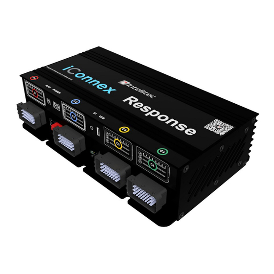
PRODUCT Response SPECIFICATION Input Voltage (Volts DC) 12/24V Max Input Current (A) Standby Current Consumption (mA) 35 mA ± 10 Isolation mode Current Consumption (mA) 0 mA IP Rating IP20 Weight (kg) 2.5 kg Dimensions L x W x D (mm) 290 x 178 x 77 INPUTS OUTPUTS... -
Page 4: Installation - Schematic
INSTALLATION Response Schematic: (mm) 11 10R - 06 12819 Page Page V1.07 20/06/2024 V2.00 05/08/2024... - Page 5 INSTALLATION Response Schematic: M6 Pan Head Screw (mm) Advised Torque (9Nm) Mounting Minimum required spacing around the unit. 11 10R - 06 12819 Page V2.00 05/08/2024...
- Page 6 INSTALLATION Response Schematic: 11 10R - 06 12819 Page V2.00 05/08/2024...
-
Page 7: Installation - Connector Plug Wiring
INSTALLATION Response Connector Plug Wiring: Connector Description CN1 Grey Connector Grey Automotive Connector Housing 24 Way Pin Out Description A1 - FET 10A Output 2 A2 - VSense 2 A3 - Telematics Positive 4 A4 - Telematics Positive 3 A5 - Telematics Positive 2 A6 - Telematics Positive 1 A7 - VSense 1 A8 - FET 10A Output 1... - Page 8 INSTALLATION Response Connector Plug Wiring: Connector Description Black Automotive Connector Housing 24 Way CN3 Black Connector Pin Out Description A1 - Relay 2 87 A2 - FET 2A Output 6 A3 - FET 2A Output 5 A4 - FET 2A Output 4 A5 - FET 2A Output 3 A6 - FET 2A Output 2 A7 - FET 2A Output 1...
- Page 9 INSTALLATION Response Connector Plug Wiring: Connector Description Red Anderson Powerpole Connector Housing Power Connector Cable Entry View 1 - + DC (Positive 30 Amp max) 2 - + DC (Positive 30 Amp max) 3 - Ground 4 - Ground Connector Description Black Anderson Powerpole Connector Housing Power Connector...
- Page 10 NOTES Response 11 10R - 06 12819 Page V2.00 05/08/2024...
-
Page 11: Multi-Functional Switch
MULTIFUNCTION Response SWITCH The switch on the front of the module is multifunctional depending on how it is interacted with. Using the information below, the different modes can be used: Hold During Power Up Erase the program form the unit. 5 Second Hold. -
Page 12: Iconnex Gui
ICONNEX GUI Response The iConnex Response and Patrol Keypads can be programmed via the iConnex GUI software package. The iConnec GUI is the utility to write and upload programs to the module. To Download the GUI please visit: www.intellitecmvcom/pages/downloads iConnex GUI So ware... -
Page 13: Module Programming
Response Connecting the Response to the GUI Use the USB on the front of the module to connect to the GUI. Ensure the iConnex Response module is powered when connecting to the GUI. GREEN is a Data status LED When the green LED is ON, that signifies there is a connection to the GUI. -
Page 14: Diagnostic Led
DIAGNOSTIC Response The module has a red, blue and green LED for diagnostic use. BLUE is a Vehicle 1, Vehicle 2 and Third Party CAN status LED When the blue LED is ON, that signifies there is CAN traffic. When the blue LED FLASHES, that signifies a CAN state change for a selected CAN message. When the blue LED is OFF, that signifies there is no CAN traffic being received GREEN is the Intelli CAN status LED... -
Page 15: Keypads
KEYPAD Response iConnex Response Patrol Keypads ICX-SW16B Type 16 Patrol Keypad - Bottom Cable Mount 8x2 Buttons ICX-SW16T Type 16 Patrol Keypad - Top Cable Mount 8x2 Buttons ICX-SW16B-14B Type 16 Patrol Keypad - Bottom Cable Mount 6x2+2 Bottom Buttons... -
Page 16: Accessories & Fitting Kit
ACCESSORIES Response iConnex Response Accessories & Fi ng Kits ICX-R-LOOM iConnex Response Installation Wiring loom ICX-R-YSC iConnex Patrol Keypad Y-Splitter Cable ICX-R-FIT iConnex Response Fitting Kit PP45 RED Anderson Power Powerpole Red Connector Housing PP45 BLACK Anderson Power Powerpole bLACK Connector Housing...
Need help?
Do you have a question about the iConnex Response and is the answer not in the manual?
Questions and answers