Advertisement
Quick Links
BATTERY CONTROL CENTER -
Product Description
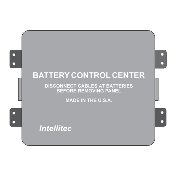
The Battery Control Center is a centralized power switching, fusing and distribution center. Power from the
Main and the Auxiliary batteries is fed into the Battery Control Center. The full power of both batteries is
available within the box. The system consists of two (2) Battery Disconnect Relays, a bi-directional battery
charging circuit, an auxiliary start function to provide a "jump start" from the Auxiliary battery, ignition power
switching and a fog light relay circuit.
All servicing of the Battery Control Center should be done only by a qualified Service Technician.
Inadvertent shorts inside the Battery Control Center could result in severe damage and/or injury.
TOOLS REQUIRED:
TO REMOVE COVER:
outward and towards yourself. The cover may then be lowered to allow easy access to the fuses and
circuitry.
Intellitec
www.intellitec.com
SERVICE MANUAL
Part Number 00-00606-100
CAUTION:
Low current Test Light, Accurate Voltmeter, (digital read-out preferred).
Gently lift the cover catches, located on each side of the box, and pull them
1
P/N 53-00606-100 Rev. D 032619
MINI DIESEL
1485 Jacobs Rd.
Deland, FL 32724
386.738.7307
Advertisement

Summary of Contents for Intellitec 00-00606-100
- Page 1 BATTERY CONTROL CENTER - MINI DIESEL SERVICE MANUAL Part Number 00-00606-100 Product Description The Battery Control Center is a centralized power switching, fusing and distribution center. Power from the Main and the Auxiliary batteries is fed into the Battery Control Center. The full power of both batteries is available within the box.
- Page 2 There are two 30 Amp circuit breakers, located near the front at the bottom of the box, that are used to protect the wiring between the Auxiliary battery and the converter. These breakers have manual reset buttons that pop out when they are tripped ( See Figure 5) 1485 Jacobs Rd. Intellitec Deland, FL 32724 386.738.7307 www.intellitec.com...
-
Page 3: Troubleshooting
To reset the breakers, turn off the 12 loads and push the buttons in until they latch. 1485 Jacobs Rd. Intellitec Deland, FL 32724 386.738.7307 www.intellitec.com... -
Page 4: Printed Circuit Board Removal
Replace the board in the reverse order from the removal. Be sure to tighten the 1/4" hex head bolt going through the board, for it provides the power connection to the battery feed. Failure to properly tighten this bolt will lead to failure. 1485 Jacobs Rd. Intellitec Deland, FL 32724 386.738.7307 www.intellitec.com... - Page 5 BATTERY CONTROL CENTER - MINI DIESEL SERVICE MANUAL MAIN BD Generator Auxiliary Battery Converter Circuit Main Battery Breakers Pictorial View Figure 1 1485 Jacobs Rd. Intellitec Deland, FL 32724 386.738.7307 www.intellitec.com P/N 53-00606-100 Rev. D 032619...
- Page 6 3. There may not be 12 volt power to the switch. If there is not 12 volts check fuse F19. Coach functions operate when coach is plugged in, but not from the battery. 1. Circuit breakers feeding converter may be open. Reset circuit breakers in box. 1485 Jacobs Rd. Intellitec Deland, FL 32724 386.738.7307 www.intellitec.com...
- Page 7 4. Switch or wires may be faulty. Check for 12 volts at J4 pin 2, while pushing switch. If there is not 12 volts, check wiring, if OK, replace the switch. 1485 Jacobs Rd. Intellitec Deland, FL 32724 386.738.7307 www.intellitec.com...
- Page 8 4. No power from the fog light switch. Check for voltage at J4, pin 12. 5. No 12 volt power to fog lights. Check for voltage at J4, pin 9. 6. Fog light relay has failed. Replace printed circuit board. 1485 Jacobs Rd. Intellitec Deland, FL 32724 386.738.7307 www.intellitec.com...
- Page 9 F12 (J12)+F22 (J17)+F23 (J18) must not exceed 30 Amps. Fog Light 15 Amp J4-9 Disconnect-Switched Auxiliary Battery Spare 15 Amp LP Detector 5 Amp J4-4 Radio Switch 10 Amp J4-1 1485 Jacobs Rd. Intellitec Deland, FL 32724 386.738.7307 www.intellitec.com P/N 53-00606-100 Rev. D 032619...
-
Page 10: Circuit Breakers
J1 - 8 pin in-line (KK-156) Function Main BD "I" terminal Main BD "S" terminal Auxiliary BD "S" terminal Auxiliary BD "I" terminal Isolator Relay "HOT" terminal Isolator Relay GROUND terminal 1485 Jacobs Rd. Intellitec Deland, FL 32724 386.738.7307 www.intellitec.com P/N 53-00606-100 Rev. D 032619... - Page 11 Fuse Radio Switch Aux Start Switch Solar Panel L. P. Det. (Aux.) Ground Fog Lights Aux Start Relay Coil Ignition Relay Coil Fog Light Relay Coil 1485 Jacobs Rd. Intellitec Deland, FL 32724 386.738.7307 www.intellitec.com P/N 53-00606-100 Rev. D 032619...
- Page 12 Power Seat Rear Heater Power Window Horn/Leveling Jacks J22 - 2 pin Mate-N-Lok Mating Housing AMP 1-480698-0 Function Fuse Isolator Relay Coil Power Isolator Relay Coil Ground 1485 Jacobs Rd. Intellitec Deland, FL 32724 386.738.7307 www.intellitec.com P/N 53-00606-100 Rev. D 032619...
- Page 13 BATTERY CONTROL CENTER - MINI DIESEL SERVICE MANUAL 1485 Jacobs Rd. Intellitec Deland, FL 32724 386.738.7307 www.intellitec.com P/N 53-00606-100 Rev. D 032619...
- Page 14 BATTERY CONTROL CENTER - MINI DIESEL SERVICE MANUAL 1485 Jacobs Rd. Intellitec Deland, FL 32724 386.738.7307 www.intellitec.com P/N 53-00606-100 Rev. D 032619...
- Page 15 BATTERY CONTROL CENTER - MINI DIESEL SERVICE MANUAL 1485 Jacobs Rd. Intellitec Deland, FL 32724 386.738.7307 www.intellitec.com P/N 53-00606-100 Rev. D 032619...
- Page 16 K1A which includes fuse F9 (J5, pin 7)+F10 (J5, pin 8)+F11 (J11) must not exceed 30 Amps, and the sum of the total continuous currents through relay K1B which includes fuse F12 (J12)+F22 (J17)+F23 (J18) must not exceed 30 Amps. 1485 Jacobs Rd. Intellitec Deland, FL 32724 386.738.7307 www.intellitec.com...
- Page 17 BATTERY CONTROL CENTER - MINI DIESEL SERVICE MANUAL 1485 Jacobs Rd. Intellitec Deland, FL 32724 386.738.7307 www.intellitec.com P/N 53-00606-100 Rev. D 032619...


Need help?
Do you have a question about the 00-00606-100 and is the answer not in the manual?
Questions and answers