
Related Manuals for FrontLine CO2NN


Summary of Contents for FrontLine CO2NN
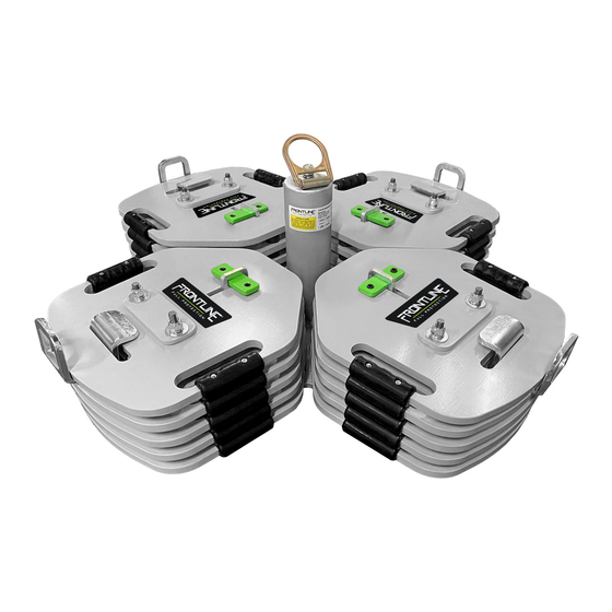
- Page 1 Instruction Manual USE R MA N UAL COUNTERWEIGHT ANCHOR SYSTEM CO2NN Meets or exceeds applicable standards Rev. Apr. 2024...
- Page 2 Instruction Manual Frontline Fall Protection Inc. INSTRUCTION MANUAL This product meets applicable OSHA 1910 and OSHA 1926 fall protection standards. These instructions apply to the following model(s): CO2NN Applicable standards and regulations depend on the type of work being done, and also might include state-specific regulations. Refer...
-
Page 3: Table Of Contents
Instruction Manual TABLE OF CONTENTS Definitions __________________________________________________________ 4 General Statement and Warnings ___________________________________ 8 Training Requirements ______________________________________________ 9 Description _________________________________________________________ 10 Application __________________________________________________________ 11 System Requirements _____________________________________________ 13 Installation _________________________________________________________ 19 Product Disassembly and Assembly _______________________________ 22 Maintenance, Service, and Storage _________________________________ 29 BUILT TO LAST | MANUFACTURED TO COMPLY | DESIGNED TO PROTECT... -
Page 4: Definitions
Instruction Manual DEFINITIONS Anchorage A secure point of attachment for lifelines, lanyards, or deceleration devices. Attachment Point A loop or “D” ring connected (integrally) to the body support that provides a means for attachment of other components of the fall protection system. Body Harness Means straps, which may be secured about the worker in a manner that will distribute the fall arrest forces over at least the thighs, pelvis, waist, chest and... - Page 5 location of that attachment point after the employee comes to a full stop. Fall Arrest System A fall arrest system means a system used to arrest an employee in a fall from a working level. It consists of an anchor point, connectors, a body belt or body harness and may include a lanyard, deceleration device, lifeline, or suitable com- binations of these.
- Page 6 Instruction Manual Leading Edge The edge of a floor, roof, or formwork for a floor or other walking or working surface (such as the deck) which changes location as additional floor, roof, decking, or formwork sections are placed, formed, or constructed. A leading edge is considered to be an “unprotected side and edge”...
- Page 7 (also referred to as a fall arrester). Self-Retracting Lifeline/Lanyard A deceleration device containing a drum-wound line, which can be slowly extracted from, or retracted onto, the drum under slight tension during normal worker movement, and which, after onset of a fall, automatically locks the drum and arrests the fall.
-
Page 8: General Statement And Warnings
User Instructions is not approved by Frontline Fall Protection and could result in serious injury or death. This device is only to be used by trained users in workplace applications. -
Page 9: Training Requirements
1,800 lbs. TRAINING REQUIREMENTS Before using Frontline Fall Protection product, user and employers must ensure that the person using this equipment has been trained on the proper use, care and maintenance of this product by a competent person qualified in Fall Protection. -
Page 10: Description
DESCRIPTION The Frontline counterweight system is a one user non-penetrating anchor meant for fall arrest or fall restraint applications when exposed to a fall hazard. This counterweight anchor is for temporary applications and comes fully assembled... -
Page 11: Application
Anchor APPLICATION This Anchorage Connector has been tested for compliance with the requirements of EN 795.2012 and OSHA Testing covers only the Anchorage Connector and does not extend to the connector, body harness, subsystem and/or substrate to which the Anchorage Connector is attached to. Prior to installation and use of this equipment, record the product identification information from the label in the Inspection and Maintenance Log at the end of this manual. - Page 12 DIMENSIONS: WEIGHT: 806 lbs Purpose: The Frontline Fall Arrest Anchors are designed to be used as a component in a Personal Fall Arrest System (PFAS) Frontline Fall Arrest Anchors are tested to meet or exceed applicable OSHA and/or ANSI standards so employees can work safely tie-off while maintaining mobility and being productive when using Anchorage Connector.
-
Page 13: System Requirements
General Disclaimer: Frontline has tested their product to comply with OSHA and/ or ANSI under a controlled environment and with certain substrates. Frontline cannot and does not guarantee the same performance for different substrates other than the ones mentioned in these user manuals. - Page 14 Instruction Manual FIGURE 2 - NON - COMPATIBLE CONNECTIONS DO NOT connect two snaphooks or DO NOT connect two snaphooks or carabiners carabiners to each other. to a single D-ring at the same time. DO NOT connect in a way that would create DO NOT attach to a object in a manner a loading on the gate.
- Page 15 NOTE: Large snap hooks must not be connected to objects which will result in a load on the gate if the hook twists or rotates, unless the snap hook complies with ANSI Z359.1-2007 or ANSI Z359.12 and is equipped with a 3,600 lb (16 kN) gate. Check the marking on your snap hook to verify its compatibility.
- Page 16 Instruction Manual • The distance the worker will travel as the deceleration device absorbs the energy from the fall (i.e., slows it down.) • The worker’s height. • D-ring shift and a safety factor. Below are illustrations to help guide the user to determine minimum fall clearances and swing hazards: BUILT TO | MANUFACTURED TO...
- Page 17 FIGURE 3 Connecting Subsystem (Energy Absorbing Lanyard Shown) Working Level Shown Lower Level or Obstruction Free Fall - 6ft. (1.8m) Max. (per ANSI Z 359.11) Deceleration Distance Total Fall Distance Free Fall (D) + Deceleration (E) BUILT TO | MANUFACTURED TO | DESIGNED TO LAST COMPLY...
- Page 18 Instruction Manual Swing Fall: The swing fall hazard is created by the pendulum effect, which can swing a fallen worker into a nearby surface, such as a wall or protruding beam. In addition to calculating the total fall clearance distance before beginning work on an elevated level, it is important to evaluate the swing fall hazard at the edges where a worker might fall.
-
Page 19: Installation
Additionally, in page 30 you have a more detailed list of the inspection requirements for this particular product. These are minimum requirements, and all inspections should be documented for recordkeeping. Any questions regarding the safety inspection of Frontline Fall Protection products please contact us at info@frontlinefall.com. INSTALLATION... - Page 20 Instruction Manual Once the work area and substrate has been verified that it can sustain such loads, then the following steps should be followed: 1. Place anchor in desired location and make sure the anchor is placed at a minimum of 8’ from the leading edge or fall hazard (Figure 6). FIGURE 6 2.
- Page 21 b. The two back indicator lines will help you center the Green Center Steel Plates (Figure 7). FIGURE 7 Back indicator lines 4. Inspect that the d-ring is swiveling freely and that the nut and washer is in place, tight and secured. 5.
-
Page 22: Product Disassembly And Assembly
Instruction Manual PRODUCT DISASSEMBLY AND ASSEMBLY If the anchor needs to be disassembled in order to transport it or for whatever other reason, then the following steps should be taken: Disassembly: 1. Ensure that the anchor is on a safe and stable location where is can be safely disassembled and worker’s are not exposed to fall hazard. - Page 23 5. Now all the Anchor Weights should be loose and you can pull them out freely by grabbing them by the Ergonomic Carry Handles (Figure 10). FIGURE 10 6. When the last Anchor Weight is removed the U - Bolt Rod will come loose and the anchor is now free to be move/transported to the desired location (Figure 11).
- Page 24 Then feed the Vertical Steel Riser slides in through the Anchor Weight as well (Figure 12). FIGURE 12 *Anchor Weight that include Frontline logo labels and that don’t have the oval opening are the top plates b. Repeat this for all the sides for the first Anchor Weights.
- Page 25 FIGURE 14 f. The last base should be the one with out the Internal Rubber Supports and with the Frontline logo facing upwards 2. Once all the Anchor Weights are correctly assembled, then slide in the Green Center Plates in-between the Vertical Riser and Anchor Weights (Figure 15).
- Page 26 Instruction Manual a. The Green Center Anchor Plates will have two black marking indicating the center marks and it should be placed right in between the Vertical Steel Riser (Figure 16). FIGURE 16 Back indicator lines b. Once its centered, screw in both socket head screws in order to put vertical pressure on the Base Plate and Anchor Weights.
- Page 27 4. Once all these seps have been performed, your anchor should be inspected for the following: a. All weights on all sides are up against each other (Figure 16). FIGURE 16 b. Green Center Steel Plates are centered between the black center lines on the Vertical Steel Risers and socket head screws are not loose and well tightened up against the Anchor Weights.
- Page 28 Frontline does NOT allow counterweight anchor to be lifted, hoisted or flown above personnel where it can create a struck by or fallen object hazard for those working beneath at lower level.
-
Page 29: Maintenance, Service, And Storage
Repairs and maintenance can only by done Frontline MAINTENANCE AND SERVICE: Fall Protection. No company or end user shall maintenance or repair Frontline Fall Protection products under no circumstances. Product that does not pass inspection or is questionable needs to be taken out of service immediately and then notified to Frontline Fall Protection for inspection and further action. - Page 30 Instruction Manual INSPECTION AND MAINTENANCE LOG INSPECTION DATE: INSPECTED BY: Inspection: Prior to installation and prior to each use / COMPONENTS: PASS FAIL Inspection by a competent person is required every 6 months. D - Ring Swiveling Anchor has a secure and tight fit and swivels ANCHORAGE: freely Inspect the Anchor for damage: Look for cracks, dents, or...
- Page 31 Additional Personal Fall Arrest System (PFAS) equipment PFAS AND (harness, SRL, etc) that are used with the Anchorage System OTHER should be installed and inspected per the manufacturer’s EQUIPMENT instructions and equipment used with this fall arrest system must limit the dynamic maximum fall forces to no greater than 1,800 lbs INSPECTION DATE: INSPECTED BY:...
- Page 32 Frontline Fall Protection Inc. www.frontlinefall.com info@frontlinefall.com ©2024 Frontline...
Need help?
Do you have a question about the CO2NN and is the answer not in the manual?
Questions and answers