
Related Manuals for First Co AE-Air WSVC Series


Summary of Contents for First Co AE-Air WSVC Series
- Page 1 Installation, Operation, & Maintenance IOM 7901 Rev. A 1/24 *WSVC/*WSVX SERIES WATER SOURCE HEAT PUMPS ATTENTION Read all instructions thoroughly and retain all manuals for future reference.
- Page 2 WSV* IOM COPYRIGHT The Manufacturer works to continually improve its products and as a result, it reserves the right to change design and specifications without notice. ***WARNING TO INSTALLER, SERVICE PERSONNEL AND OWNER*** Altering the product or replacing parts with non-authorized factory parts voids all warranty or implied warranty and may result in adverse operational performance and/or a possible hazardous condition to service personnel and occupants.
-
Page 3: Table Of Contents
WSV* IOM TABLE OF CONTENTS SAFETY CONSIDERATIONS GENERAL INFORMATION INTRODUCTION INSTALLATION 6-11 INSTALLATION PRECAUTIONS LOCATION/MOUNTING CONDENSATE DRAIN FILTER BRACKETS AIR DISTRIBUTION DUCTS ELECTRICAL CONNECTIONS THERMOSTAT CONTROL MODULE AND SAFETY DEVICES 9-10 PIPING 10-11 SYSTEM APPLICATIONS COOLING TOWER/BOILER APPLICATION 13-14 UNIT CONNECTIONS EXTENDED RANGE OPERATION WELL WATER APPLICATIONS EARTH COUPLED SYSTEMS... -
Page 4: Safety Considerations
WSV* IOM SAFETY CONSIDERATIONS 1. READ THE ENTIRE MANUAL BEFORE STARTING THE INSTALLATION. 2. Improper installation, adjustment, alteration, service, maintenance, or use can cause explosion, fire, electrical shock, or other conditions which may cause personal injury damage. 3. Consult a qualified licensed installer, service agency, or your distributor for information assistance. The qualified licensed installer or service agency must use factory-authorized kits or accessories when servicing this product. -
Page 5: General Information
WSV* IOM GENERAL INFORMATION The manufacturer assumes no responsibility for CAUTION equipment installed in violation of any code R-410A Systems operate at higher pressures than standard requirement. R-22 systems. Do not use R-22 service equipment or These instructions give information relative to the components on R-410A equipment. -
Page 6: Installation
WSV* IOM INTRODUCTION (CONTINUED) Check filter media installation to ensure that it is Cooling Tower/Boiler and Geo Thermal Applications installed correctly. Use the directional arrows or other should have sufficient antifreeze solution when required information on the filter to determine the proper flow to protect against extreme conditions and equipment direction. -
Page 7: Condensate Drain
WSV* IOM INSTALLATION (CONTINUED) CONDENSATE DRAIN The condensate drain must be in conformance with all plumbing codes. The condensate drain must be connected to the heat pump and pitched away from the unit a minimum 1/8” per foot to allow the condensate to flow away from the unit. -
Page 8: Filter Brackets
WSV* IOM INSTALLATION (CONTINUED) FILTER BRACKETS Figure 1- Filter Bracket Detail WARNING Filter brackets are shipped within the unit, they are located within the blower compartment and must be mounted to the external cabinet prior to mounting/installing the unit. Refer to Figure 1 – Filter Bracket Detail. *WSVC/*WSVX SERIES IOM (Rev. -
Page 9: Air Distribution Ducts
WSV* IOM INSTALLATION (CONTINUED) AIR DISTRIBUTION DUCTS WARNING All duct work must be installed in accordance with National Fire Protection Association Codes 90A and 90B. Three phase units are supplied with phase monitors which Ducts should be adequately insulated to prevent restrict power from being applied out of phase, unbalanced or when there is a loss of phase. -
Page 10: Piping
WSV* IOM INSTALLATION (CONTINUED) LED Display – A two digit display indicates the Low Pressure Bypass Timer – The low pressure system mode and fault code, if present. switch input is bypassed for the initial 120 seconds See table 1. of a compressor run cycle to prevent nuisance low CONTROLLER OPERATIONAL CODES DESCRIPTION OF OPERATION... - Page 11 WSV* IOM INSTALLATION (CONTINUED) Units are supplied with either a copper or optional Ball valves should be installed in the supply and return cupro-nickel water to refrigerant heat exchangers. lines for unit isolation and unit water flow balancing. Copper is adequate for ground water that is not high in Pressure/temperature ports are recommended in both mineral content.
-
Page 12: System Applications
WSV* IOM SYSTEM APPLICATIONS COOLING TOWER/BOILER APPLICATION A secondary heat exchanger (plate frame between the To assure optimum cooling and heating performance, unit and the open cooling tower) may also be used. It is the cooling tower and boiler water loop temperature imperative that all air is eliminated from the closed loop should be maintained between 55-75 degrees F in the side of the heat exchanger to prevent condenser fouling. -
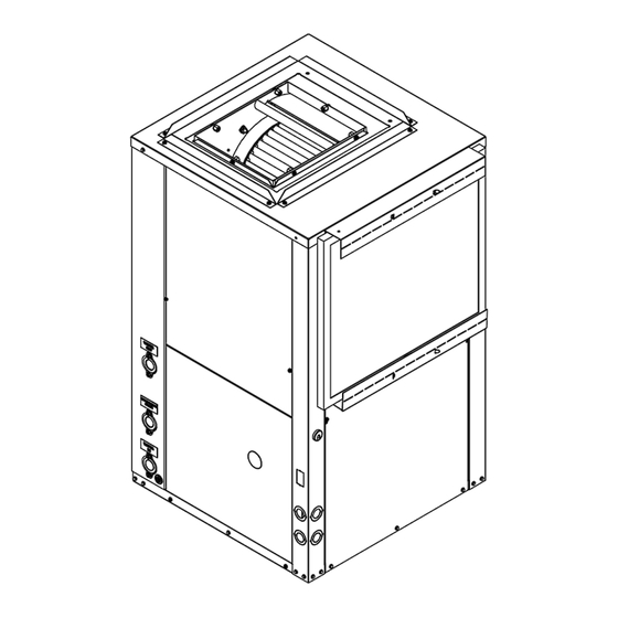
Page 13: Unit Connections
WSV* IOM UNIT CONNECTIONS Figure 2- Right Hand Model Shown *WSVC/*WSVX SERIES IOM (Rev. A 1/24) -
Page 14: Extended Range Operation
WSV* IOM EXTENDED RANGE OPERATION: EARTH COUPLED SYSTEMS Piping systems expected to utilize water temperatures below 50 degrees require the extended range option WARNING which includes closed cell insulation on all piping surfaces to eliminate condensation. This application Closed loop and pond applications require specialized design requires sufficient antifreeze solution to protect the knowledge. -
Page 15: System Check-Out & Start-Up
WSV* IOM SYSTEM CHECK-OUT & START - UP UNIT START-UP SYSTEM CHECK-OUT Set the thermostat to its highest setting. After completing the installation and before energizing Set the thermostat system switch to “COOL” and the unit, the following system checks should be made: the fan switch to the “AUTO”... -
Page 16: Blower Speed Selection
WSV* IOM BLOWER SPEED SELECTION UNITS with PSC MOTOR All units have a 3 or 4 speed motor so the blower can be field adjusted to a higher speed tab when the system application has higher static requirements. Refer to the unit specification sheet and wiring diagram for speed selections. -
Page 17: System Maintenance
WSV* IOM SYSTEM MAINTENANCE To ensure maximum performance and service life of Periodic lockouts almost always are caused by air or equipment, a formal schedule of regular preventative water problems. The lockout (shutdown) of the unit is a maintenance must be established and adhered to. normal protective measure in the design of the equipment. -
Page 18: Operating Temperatures & Pressures
WSV* IOM OPERATING TEMPERATURES & PRESSURES OPERATING DATA COOLING HEATING ENTERING WATER SUCTION DISCHARGE WATER SUCTION DISCHARGE WATER MODEL WATER FLOW PRESSURE PRESSURE TEMP TEMP PRESSURE PRESSURE TEMP TEMP TEMP, F PSIG PSIG RISE, F DROP, F PSIG PSIG DROP, F RISE, F 114 - 124 173 - 223... - Page 19 WSV* IOM OPERATING TEMPERATURES & PRESSURES (CONTINUED) OPERATING DATA COOLING HEATING ENTERING WATER SUCTION DISCHARGE WATER SUCTION DISCHARGE WATER MODEL WATER FLOW PRESSURE PRESSURE TEMP TEMP PRESSURE PRESSURE TEMP TEMP TEMP, F PSIG PSIG RISE, F DROP, F PSIG PSIG DROP, F RISE, F 112 -152...
- Page 20 WSV* IOM OPERATING TEMPERATURES & PRESSURES (CONTINUED) OPERATING DATA COOLING HEATING ENTERING WATER SUCTION DISCHARGE WATER SUCTION DISCHARGE WATER MODEL WATER FLOW PRESSURE PRESSURE TEMP TEMP PRESSURE PRESSURE TEMP TEMP TEMP, F PSIG PSIG RISE, F DROP, F PSIG PSIG DROP, F RISE, F 110 - 150...
- Page 21 WSV* IOM OPERATING TEMPERATURES & PRESSURES (CONTINUED) OPERATING DATA COOLING HEATING ENTERING WATER SUCTION DISCHARGE WATER SUCTION DISCHARGE WATER MODEL WATER FLOW PRESSURE PRESSURE TEMP TEMP PRESSURE PRESSURE TEMP TEMP TEMP, F PSIG PSIG RISE, F DROP, F PSIG PSIG DROP, F RISE, F 106 - 146...
- Page 22 WSV* IOM CAUTION High efficiency brushless DC motors are wired with power applied at all times (X13 for example, see illustration above). Low voltage thermostat demand and board algorithms will control its use. *WSVC/*WSVX SERIES IOM (Rev. A 1/24)
-
Page 23: Wiring Diagrams
WSV* IOM WIRING DIAGRAMS Figure 3- WD79P014 Figure 4- WD79P013 *WSVC/*WSVX SERIES IOM (Rev. A 1/24) - Page 24 WSV* IOM WIRING DIAGRAMS (CONTINUED) Figure 5- WD79P008 Figure 6- WD79P009 *WSVC/*WSVX SERIES IOM (Rev. A 1/24)
- Page 25 WSV* IOM WIRING DIAGRAMS (CONTINUED) Figure 7- WD79P010 Figure 8- WD79X001 *WSVC/*WSVX SERIES IOM (Rev. A 1/24)
- Page 26 WSV* IOM WIRING DIAGRAMS (CONTINUED) Figure 9- WD79X003 *WSVC/*WSVX SERIES IOM (Rev. A 1/24)
-
Page 27: Unit Check-Out Sheet
WSV* IOM UNIT CHECK-OUT SHEET *WSVC/*WSVX SERIES IOM (Rev. A 1/24) -
Page 28: Notes
WSV* IOM NOTES *WSVC/*WSVX SERIES IOM (Rev. A 1/24) - Page 29 P.O. Box 270969 Dallas, TX 75227 www.firstco.com or www.ae-air.com The manufacturer works to continually improve its products. It reserves the right to change design and specifications without notice. ©2022 First Co., Applied Environmental Air...
Need help?
Do you have a question about the AE-Air WSVC Series and is the answer not in the manual?
Questions and answers