Advertisement
Quick Links
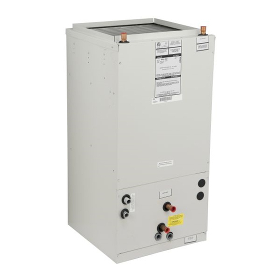
VMB-HW
INSTALLATION, OPERATION & MAINTENANCE INSTRUCTIONS
**WARNING TO INSTALLER, SERVICE PERSONNEL AND OWNER**
Altering the product or replacing parts with non authorized factory parts voids all warranty or implied warranty
and may result in adverse operational performance and/or a possible hazardous safety condition to service
personnel and occupants. Company employees and/or contractors are not authorized to waive this warning.
Current
is available at
under "Product Information".
SAFETY CONSIDERATIONS
1
Advertisement

Related Manuals for First Co VMB-HW


Summary of Contents for First Co VMB-HW
- Page 1 VMB-HW INSTALLATION, OPERATION & MAINTENANCE INSTRUCTIONS **WARNING TO INSTALLER, SERVICE PERSONNEL AND OWNER** Altering the product or replacing parts with non authorized factory parts voids all warranty or implied warranty and may result in adverse operational performance and/or a possible hazardous safety condition to service personnel and occupants.
-
Page 2: Installation
GENERAL INTRODUCTION INSTALLATION NOTE: The variable speed unit is compatible with damper duct systems when designed properly. Consult the damper system manufacturer for proper design. - Page 3 FIELD SUPPLIED SUPPLY DUCT POWER ENTRY OPTIONS (LOW VOLTAGE ENTRY OPPOSITE SIDE) HORIZONTAL POSITION LEFT SIDE DOWN CONDENSATE DRAIN FILTER ACCESS PANEL FIELD SUPPLIED RETURN PLENUM VERTICAL POSITION CONDENSATE DRAIN Figure 2 - Typical Unit Configuration...
- Page 5 FAN COIL INDOOR THERMOSTAT CONNECTIONS 24V CHILLED WATER VALVE 24V HOT WATER VALVE DEHUM. Figure 3 - Low Voltage Wiring Connections...
- Page 7 1-1/2" MIN UNIT 1-1/2" MIN...
- Page 9 Remove the motor blower shipping brace on the 20MB-HW blower assembly. Failure to do so will cause damage to the unit. NOTE: The variable speed unit is compatible with damper duct systems when designed properly. Consult the damper system manufacturer for proper design. Thermostat Terminals Control Board Select Taps Model...
- Page 10 D – NOTE: The unit does NOT read changes in COOL, HEAT, and DELAY taps while it is running. Disconnect power for 1 minute before changing taps, then restart for the new settings to take affect.
- Page 11 TEST HEAT COOL DEHUMIDIFY C C1 R HUM CUT TO ENABLE...
- Page 12 FIRST CO. -- CB600 DELAY ADJUST C1 (RCom) NORM TEST HEAT COOL DEHUMIDIFY Y2 Y1 G O W1 W2 NC C1 R HUM CUT TO ENABLE Do not assume the motor or module is defective if it will not start.
- Page 13 16-Pin Motor Wiring Harness to 16-Pin Connector on Select Board Pin # on Signal on pin with Description 16-Pin Screw Terminal Connector Jumpered to R * Common W /W1 Heating Signal 24VAC ** Common Delay Adjust Cool Fan Adjust Cooling Signal (-) 12VDC ** CFM Adjust Not Used...
- Page 14 D. Verify Motor Winding Section: www.firstco.com...
- Page 15 Maintenance Updates A current copy of the Maintenance Program log can be found at www.firstco.com under “Product Informa- tion”.
Need help?
Do you have a question about the VMB-HW and is the answer not in the manual?
Questions and answers
blower motor was making noises shut down now it just hums check motor turns free no burnt smell
If the First Co VMB-HW blower motor hums but does not turn on and there are no burnt smells, the issue could be a failed or weak capacitor. The capacitor helps start the motor, and if it's faulty, the motor may hum but not spin. Another possible cause is a stuck or seized motor bearing, which prevents rotation despite power being applied.
This answer is automatically generated