
Related Manuals for First Co AE-Air HydroTech WSV6 009 Series


Summary of Contents for First Co AE-Air HydroTech WSV6 009 Series
- Page 1 Installation, Operation, & Maintenance Manual IOM 8001 Rev. J 3/23 WSV6 009-072 Vertical Series Water Source Heat Pump...
- Page 2 WSV6 VERTICAL SERIES - IOM COPYRIGHT First Co. / AE-Air works to continuously improve its products and as a result, it reserves the right to change design and specifications without notice. The warranty may be void unless the Startup & Performance Checklist is completed and returned to the warrantor. If the HVAC unit is not installed properly, the warranty will be void, as the manufacturer cannot be held accountable for problems that stem from improper installation.
-
Page 3: Table Of Contents
WSV6 VERTICAL SERIES TABLE OF CONTENTS SAFETY CONSIDERATIONS MODEL NOMENCLATURE GENERAL INFORMATION INTRODUCTION STORAGE SHIPPING & PACKAGE LIST UNIT INSPECTION CHECKLIST UNIT DIMENSIONAL DATA 10-14 UNIT PHYSICAL DATA ELECTRICAL DATA INSTALLATION 16-23 ELECTRICAL APPLICATION 25-29 CONTROLS 30-36 PERFORMANCE DATA 37-48 WIRING DIAGRAMS 49-55 CIRCUIT SCHEMATIC... -
Page 4: Safety Considerations
WSV6 VERTICAL SERIES - IOM SAFETY CONSIDERATIONS 1. READ THE ENTIRE MANUAL BEFORE STARTING THE INSTALLATION. 2. These instructions are intended as a general guide and do not supersede national, state, or local codes in any way. 3. Altering the product, improper installation, or the use of unauthorized factory parts voids all warranty or implied warranty and may result in adverse operation and/or performance or may result in hazardous conditions to service personnel and occupants. - Page 5 WSV6 VERTICAL SERIES SAFETY CONSIDERATIONS CONTINUED Mechanical components and filters can become clogged with dirt and debris, which can cause damage to the system. These instructions are intended as an aid to qualified, The manufacturer does not warrant equipment subjected to licensed service personnel for proper installation, adjustment abuse.
-
Page 6: Model Nomenclature
WSV6 VERTICAL SERIES - IOM MODEL NOMENCLATURE FIGURE 1 – Model Nomenclature WSV6 Vertical Series – IOM... -
Page 7: General Information
WSV6 VERTICAL SERIES GENERAL INFORMATION DO NOT use these units as a source of heating or cooling Extreme caution must be taken that no internal damage during the construction process. Mechanical components will result from screws that are drilled into the cabinet. and filters can become clogged with dirt and debris, which can cause damage to the system. -
Page 8: Storage
WSV6 VERTICAL SERIES - IOM STORAGE Equipment should be stored in a clean dry, conditioned area with maximum temperatures up to 120°F [48.89°C] and minimum temperatures to 32°F [0°C]. Units should be stored upright and in an indoor environment. It is recommended to leave packaging on the unit until the installation is to begin. -
Page 9: Unit Inspection Checklist
WSV6 VERTICAL SERIES UNIT INSPECTION CHECKLIST Complete the inspection procedures below before preparing unit for installation: 1) Visually inspect unit for any shipping damage. Damage must be reported immediately to the shipping company to make a claim. 2) Ensure that the carrier makes proper notation of any shortages or damage on all copies of the freight bill and completes a common carrier inspection report. -
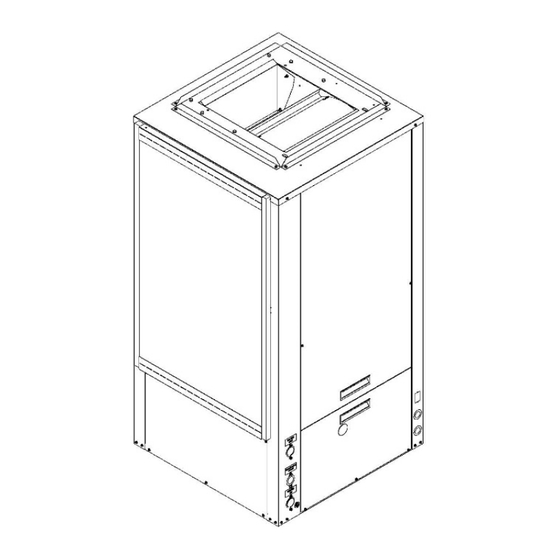
Page 10: Unit Dimensional Data
WSV6 VERTICAL SERIES - IOM UNIT DIMENSIONAL DATA FIGURE 4 – Unit Dimensions WSV6 Vertical Series – IOM... - Page 11 WSV6 VERTICAL SERIES UNIT DIMENSIONAL DATA CONTINUED DIMENSIONAL DATA OVERALL CABINET SUPPLY CONNECTIONS MODEL WSV6009 21.50 21.50 36.25 9.50 7.75 4.25 4.50 12.75 4.25 WSV6012 21.50 21.50 36.25 9.50 7.75 4.25 4.50 12.75 4.25 WSV6018 21.50 21.50 36.25 5.50 13.75 2.25 3.50 16.25...
- Page 12 WSV6 VERTICAL SERIES - IOM UNIT DIMENSIONAL DATA - ECONOMIZER FIGURE 5 – Unit Dimensions – Economizer RH WSV6 Vertical Series – IOM...
- Page 13 WSV6 VERTICAL SERIES UNIT DIMENSIONAL DATA - ECONOMIZER CONTINUED FIGURE 6 – Unit Dimensions – Economizer LH WSV6 Vertical Series – IOM...
-
Page 14: Unit Physical Data
WSV6 VERTICAL SERIES - IOM UNIT DIMENSIONAL DATA - ECONOMIZER CONTINUED DIMENSIONAL DATA - ECONOMIZER A’ MODEL 1” 2” WSV6048 31.59 0.91 1.91 30.39 29.82 43.16 2.72 6.22 10.72 16.72 5.25 18.88 1.92 2.38 18.88 4.77 WSV6060 31.59 0.91 1.91 30.39 29.82 51.20 2.72 6.22 10.72 16.72 5.25 18.88 1.92 2.38 18.88 4.77 WSV6072... -
Page 15: Electrical Data
WSV6 VERTICAL SERIES ELECTRICAL DATA ELECTRICAL DATA BLOWER MIN. MAX. COMPRESSOR MODEL VOLTAGE-PH-HZ MOTOR CIRCUIT CIRCUIT AMPACITY PROTECTION 208/230-1-60 WSV6009 265-1-60 208/230-1-60 WSV6012 265-1-60 208/230-1-60 56.3 WSV6018 265-1-60 208/230-1-60 10.9 62.9 265-1-60 WSV6024 208/230-3-60 55.4 460-3-60 208/230-1-60 15.4 82.6 265-1-60 12.2 WSV6030 208/230-3-60... -
Page 16: Installation
WSV6 VERTICAL SERIES - IOM INSTALLATION REQUIREMENTS Follow manufacturer’s installation instructions, as well as local and municipal building codes. INSTALLATION PRECAUTIONS Insulation is installed in the unit to provide a barrier between varying atmospheres outside and within the unit. If insulation is damaged condensation can occur and can lead to corrosion, component failure, and possible Always wear all appropriate personal protection... - Page 17 WSV6 VERTICAL SERIES INSTALLATION CONTINUED UNIT CLEARANCE REQUIREMENTS FIGURE 7 – Unit Clearance Requirements MOUNTING DETAILS Locate the unit in an area that provides minimum clearance accesses as specified by FIGURE 7 – Unit Clearance Requirements . Also, refer to this figure for detailed information on unit dimensional sizes. Consider all additional clearances needed for water connections, electrical connections, duct connections and sufficient return airflow.
- Page 18 WSV6 VERTICAL SERIES - IOM INSTALLATION CONTINUED MOUNTING DETAILS CONTINUED FIGURE 8 – Mounting Installation WSV6 Vertical Series – IOM...
- Page 19 WSV6 VERTICAL SERIES INSTALLATION CONTINUED FILTER BRACKETS FIGURE 9 – Filter Bracket Detail Filter brackets are shipped within unit, they are located Remove shipping blocks from under blower housing within the blower compartment and must be mounted to before installing the unit.
- Page 20 WSV6 VERTICAL SERIES - IOM INSTALLATION CONTINUED PIPING NOTES PIPING INSTALLATION All piping must be adequately sized to meet the designed water flow as specified for the specific application, and must adhere to all applicable codes. Piping connections on the equipment are not necessarily indicative of the proper Prior to making piping connections, contractor must clean supply and return line sizes.
- Page 21 WSV6 VERTICAL SERIES INSTALLATION CONTINUED piping will be routed through areas subject to freezing, PIPING INSTALLATION CONTINUED antifreeze is needed. Alcohols and glycols are commonly used as antifreeze agents. Freeze protection should be maintained to 15°F below the lowest expected entering loop temperature.
- Page 22 WSV6 VERTICAL SERIES - IOM INSTALLATION CONTINUED CONDENSATE DRAINAGE Condensate drain lines must be properly installed with adequate slope away from unit to ensure proper drainage. A minimum trap of 1.5 inches must be installed to isolate the negative pressures of the drain pan from the drain line. Refer to Figure 10 Condensate Drainage for schematic –...
- Page 23 WSV6 VERTICAL SERIES INSTALLATION CONTINUED DISCHARGE DUCTING All ductwork should conform to industry standards of good practice as described in ASHRAE System Guide. A field supplied discharge duct system will normally consist of flexible connector at the unit, a non-insulated transition piece to the full duct size, a short run of duct, an elbow without vanes and a trunk duct teeing into a branch circuit with discharge diffusers as shown in...
-
Page 24: Electrical
WSV6 VERTICAL SERIES - IOM ELECTRICAL HIGH VOLTAGE LOW VOLTAGE THERMOSTAT A standard 24 VAC Heat Pump thermostat is required that will operate the reversing valve in the cooling mode. Disconnect all power supplies before servicing. Lock Thermostat connections and their functions are below in out/tag out to prevent accidental electrical shock. -
Page 25: Application
WSV6 VERTICAL SERIES APPLICATION COOLING TOWER/BOILER APPLICATION EXTENDED RANGE OPERATION To ensure optimum cooling and heating performance, the cooling tower and boiler loop temperature should be Piping systems expected to utilize water temperature maintained between 55-75°F in the heating mode and 60- below 50°F require the extended range option, which 95°F in the cooling mode. - Page 26 WSV6 VERTICAL SERIES - IOM APPLICATION CONTINUED WATER WELL APPLICATION REQUIREMENTS: 50° Minimum Entering Water Temperature Cupronickel Refrigerant Heat Exchanger When a water well is used exclusively for supplying water to the heat pump, a cupronickel refrigerant heat exchanger is required and the well pump should operate only when the heat pump operate.
- Page 27 WSV6 VERTICAL SERIES APPLICATION CONTINUED ECONOMIZER OVERVIEW In large commercial buildings, it is common for simultaneous heating and cooling loads to be required during the winter and shoulder seasons. In order to balance the need for different heating and cooling loads, an economizer can be used to provide “free”...
- Page 28 WSV6 VERTICAL SERIES - IOM APPLICATION CONTINUED HOT GAS REHEAT DEHUMIDIFICATION OVERVIEW Because ventilation air is introduced into buildings, indoor air quality (IAQ) and relative humidity (RH) are important issues to address in selecting heating and cooling equipment. With the Hydrotech WSV6 hot gas reheat dehumidification option, the return air from space is conditioned by a dedicated air-to-refrigerant coil and then reheated by a reheat coil to control space temperature and reduce space relative humidity.
- Page 29 WSV6 VERTICAL SERIES APPLICATION CONTINUED ANTIFREEZE CORRECTION FACTORS DATA ETHYLENE GLYCOL ANTIFREEZE COOLING CAPACITY 0.995 0.992 0.987 0.983 0.979 HEATING CAPACITY 0.991 0.982 0.977 0.969 0.961 PRESSURE DROP 1.070 1.130 1.180 1.260 1.280 Table 8 - Antifreeze Correction Factors Ethylene Gycol PROPYLENE GLYCOL ANTIFREEZE COOLING CAPACITY...
-
Page 30: Controls
WSV6 VERTICAL SERIES - IOM CONTROLS SEQUENCE OF OPERATION INITIAL CONDITION: START Comp = Off; Fan = Off AWAY CHIP = NOT INSERT LEGEND: Y = Call for Cooling Y = ON G = ON STAND BY G = Call for Fan HPS –... - Page 31 WSV6 VERTICAL SERIES CONTROLS CONTINUED WSCM CONTROL MODULE CONTROL FEATURES Anti-short Cycle Protection Test mode will be automatically exited after a 10 minute Random Start period. High and low Pressure Cut-out Water Coil Low Temperature Cut-out ...
- Page 32 WSV6 VERTICAL SERIES - IOM CONTROLS CONTINUED FIELD CONTROLLABLE FUNCTIONS HOME SELECTION DEHUMIDIFICATION MODE If the switch is in the HOME position the heat pump will The system can operate in Dehumidification mode by operate in its normal mode . switching Dip 1.4 on the WSCM module.
- Page 33 WSV6 VERTICAL SERIES CONTROLS CONTINUED WSCM SAFETY FEATURES CONDENSATE OVERFLOW SENSOR The condensate overflow sensor must sense overflow levels for 30 continuous second to initiate a COF fault. The condensate overflow sensor will be monitored during the compressor run cycle. LOW PRESSURE The low pressure switch must be open and remain open for 30 continuous seconds during the “on”...
- Page 34 WSV6 VERTICAL SERIES - IOM CONTROLS CONTINUED ELECTRONIC TEMPERATURE CONTROLLER ECONOMIZER PARAMETER CODES AND (ECONOMIZER) MODES OF OPERATION RELAY OFF TEMPERATURE (OFF) The electronic temperature controller must be configured Select the temperature in which the 3-way valve de- prior to the initial unit start-up in order for the economizer energizes and the unit returns to cooling mode.
- Page 35 WSV6 VERTICAL SERIES CONTROLS CONTINUED WSCM SAFETY FEATURES CONTROLLER OPERATION CODES CONTROL BOARD LAYOUT LEGEND DESCRIPTION OF OPERATION INPUT READOUT CONNECTION DESCRIPTION OUTPUT Normal Mode (Green Light) 24 VAC 24 VAC (Grounded Common) Controller Non Functional Input Call for Compressor (Green Light) Input Call for Heating or Emergency Heat Test Mode (pins shorted momentarily)
- Page 36 WSV6 VERTICAL SERIES - IOM CONTROLS CONTINUED WSCM SAFETY FEATURES WSCM DIP SWITCH FUNCTIONS ASSEMBLY FUNCTION Once box is removed completely, line up the control panel DIP SWITCH 1 back in place of the unit and tighten screws on the base Compressor Delay No Delay 5s Delay...
-
Page 37: Performance Data
WSV6 VERTICAL SERIES PERFORMANCE DATA BLOWER DATA BLOWER DATA FACTORY BLOWER BLOWER DATA SETTINGS CFM VS. STATIC PRESSURE (in. w.g.) COOLING MODEL RATED HEATING 1-10 NUMBER SPEED AIRFLOW WSV6009 WSV6012 WSV6018 WSV6024 1,160 1,130 1,100 1,070 1,040 1,010 WSV6030 1,040 1,000 1,380 1,350 1,320 1,290 1,270 1,240 1,210 1,180 1,150 1,120 WSV6036 1150... - Page 38 WSV6 VERTICAL SERIES - IOM PERFORMANCE DATA CONTINUED PRESSURE & TEMPERATURE DATA WSV6009 PRESSURE & TEMPERATURE DATA COOLING HEATING Entering Water Flow Water Suction Discharge Air Temp Water Suction Discharge Air Temp Water Rate Temp Pressure Pressure Drop Temp Rise Pressure Pressure Drop...
- Page 39 WSV6 VERTICAL SERIES PERFORMANCE DATA CONTINUED PRESSURE & TEMPERATURE DATA WSV6012 PRESSURE & TEMPERATURE DATA COOLING HEATING Entering Water Flow Water Suction Discharge Air Temp Water Suction Discharge Air Temp Water Rate Temp Pressure Pressure Drop Temp Rise Pressure Pressure Drop Temp Rise °F...
- Page 40 WSV6 VERTICAL SERIES - IOM PERFORMANCE DATA CONTINUED PRESSURE & TEMPERATURE DATA WSV6018 PRESSURE & TEMPERATURE DATA COOLING HEATING Entering Water Flow Water Suction Discharge Air Temp Water Suction Discharge Air Temp Water Rate Temp Pressure Pressure Drop Temp Rise Pressure Pressure Drop...
- Page 41 WSV6 VERTICAL SERIES PERFORMANCE DATA CONTINUED PRESSURE & TEMPERATURE DATA WSV6024 PRESSURE & TEMPERATURE DATA COOLING HEATING Entering Water Flow Water Suction Discharge Air Temp Water Suction Discharge Air Temp Water Rate Temp Pressure Pressure Drop Temp Rise Pressure Pressure Drop Temp Rise °F...
- Page 42 WSV6 VERTICAL SERIES - IOM PERFORMANCE DATA CONTINUED PRESSURE & TEMPERATURE DATA WSV6030 PRESSURE & TEMPERATURE DATA COOLING HEATING Entering Water Flow Water Suction Discharge Air Temp Water Suction Discharge Air Temp Water Rate Temp Pressure Pressure Drop Temp Rise Pressure Pressure Drop...
- Page 43 WSV6 VERTICAL SERIES PERFORMANCE DATA CONTINUED PRESSURE & TEMPERATURE DATA WSV6036 PRESSURE & TEMPERATURE DATA COOLING HEATING Entering Water Flow Water Suction Discharge Air Temp Water Suction Discharge Air Temp Water Rate Temp Pressure Pressure Drop Temp Rise Pressure Pressure Drop Temp Rise °F...
- Page 44 WSV6 VERTICAL SERIES - IOM PERFORMANCE DATA CONTINUED PRESSURE & TEMPERATURE DATA WSV6042 PRESSURE & TEMPERATURE DATA COOLING HEATING Entering Water Flow Water Suction Discharge Air Temp Water Suction Discharge Air Temp Water Rate Temp Pressure Pressure Drop Temp Rise Pressure Pressure Drop...
- Page 45 WSV6 VERTICAL SERIES PERFORMANCE DATA CONTINUED PRESSURE & TEMPERATURE DATA WSV6048 PRESSURE & TEMPERATURE DATA COOLING HEATING Entering Water Flow Water Suction Discharge Air Temp Water Suction Discharge Air Temp Water Rate Temp Pressure Pressure Drop Temp Rise Pressure Pressure Drop Temp Rise °F...
- Page 46 WSV6 VERTICAL SERIES - IOM PERFORMANCE DATA CONTINUED PRESSURE & TEMPERATURE DATA WSV6060 PRESSURE & TEMPERATURE DATA COOLING HEATING Entering Water Flow Water Suction Discharge Air Temp Water Suction Discharge Air Temp Water Rate Temp Pressure Pressure Drop Temp Rise Pressure Pressure Drop...
- Page 47 WSV6 VERTICAL SERIES PERFORMANCE DATA CONTINUED PRESSURE & TEMPERATURE DATA WSV6072 PRESSURE & TEMPERATURE DATA COOLING HEATING Entering Water Flow Water Suction Discharge Air Temp Water Suction Discharge Air Temp Water Rate Temp Pressure Pressure Drop Temp Rise Pressure Pressure Drop Temp Rise °F...
- Page 48 WSV6 VERTICAL SERIES - IOM PERFORMANCE DATA CONTINUED WATER PRESSURE DROP DATA WATER FLOW PRESSURE DROP DATA Flow Rate (GPM) WSV6009 Pressure Drop Flow Rate (GPM) WSV6012 Pressure Drop 10.9 Flow Rate (GPM) WSV6018 Pressure Drop 10.9 Flow Rate 10.0 11.0 WSV6024 (GPM)
-
Page 49: Wiring Diagrams
WSV6 VERTICAL SERIES WIRING DIAGRAMS WSV6 Vertical Series – IOM... - Page 50 WSV6 VERTICAL SERIES - IOM WIRING DIAGRAMS WSV6 Vertical Series – IOM...
- Page 51 WSV6 VERTICAL SERIES WIRING DIAGRAMS WSV6 Vertical Series – IOM...
- Page 52 WSV6 VERTICAL SERIES - IOM WIRING DIAGRAMS WSV6 Vertical Series – IOM...
- Page 53 WSV6 VERTICAL SERIES WIRING DIAGRAMS WSV6 Vertical Series – IOM...
- Page 54 WSV6 VERTICAL SERIES - IOM WIRING DIAGRAMS WSV6 Vertical Series – IOM...
- Page 55 WSV6 VERTICAL SERIES WIRING DIAGRAMS WSV6 Vertical Series – IOM...
-
Page 56: Circuit Schematic
WSV6 VERTICAL SERIES - IOM CIRCUIT SCHEMATIC FIGURE 26 - Circuit Diagram WSV6 Vertical Series – IOM... -
Page 57: Startup Instructions
WSV6 VERTICAL SERIES CIRCUIT SCHEMATIC HGRH FIGURE 27 - Circuit Diagram HGRH STARTUP INSTRUCTIONS activities occur. Protect the equipment from debris during PRE-STARTUP CHECKS: these construction phases. PRIOR TO THE STARTUP OF THE UNIT: Electrically ground the unit. Connect ground wire to 1. -
Page 58: Startup & Performance Checklist Instructions
WSV6 VERTICAL SERIES - IOM STARTUP INSTRUCTIONS CONTINUED 11. Check for vibrations, leaks, etc. PRIOR TO THE STARTUP OF THE UNIT: 12. Verify water flow rate is correct according to 9. Check that the water coil and piping had been leak specification. -
Page 59: Maintenance & Service
WSV6 VERTICAL SERIES MAINTENANCE & SERVICE PREVENTIVE MAINTENANCE CLEANING/FLUSHING Before the unit is connected to the supply water, the water To achieve maximum performance and service life of circulating system must be cleaned and flushed to remove equipment, a formal schedule of regular maintenance any dirt or debris for the system. -
Page 60: Troubleshooting
WSV6 VERTICAL SERIES - IOM TROUBLESHOOTING PROBLEM POSSIBLE CAUSE CHECKS & CORRECTIONS Power supply off Apply power; close disconnect. Blown Fuse Replace fuse or reset circuit breaker. Check for correct fuses. If voltage is below minimum voltage specified on unit dataplate, Voltage supply low contact lower power company. - Page 61 WSV6 VERTICAL SERIES TROUBLESHOOTING CONTINUED PROBLEM POSSIBLE CAUSE CHECKS & CORRECTIONS Unit oversized Recalculate heating and cooling loads. Thermostat installed near a supply air register, relocate thermostat. UNIT SHORT Thermostat Check heat anticipator. CYCLES Loose connections in the wiring or a defective compressor Wiring and controls contactor.
-
Page 62: Support/Reference Material
WSV6 VERTICAL SERIES - IOM SUPPORT/REFERENCE MATERIAL REFERENCE CALCULATIONS ABBREVIATIONS & DEFINITIONS HEATING LDB = Leaving air temperature dry bulb °F EDB = Entering air temperature dry bulb °F LDB = EDB + GPM x 500 GPM = Water flow rate gallons per minute CFM = Airflow rate cubic feet per minute LWT = EAT + cfm x 1.08... -
Page 63: Startup & Performance Checklist
WSV6 VERTICAL SERIES STARTUP & PERFORMANCE CHECKLIST FIGURE 28 – Startup & Performance Checklist WSV6 Vertical Series – IOM... -
Page 64: Notes
WSV6 VERTICAL SERIES - IOM NOTES WSV6 Vertical Series – IOM... - Page 65 P.O. Box 270969 Dallas, TX 75227 www.firstco.com or www.ae-air.com The manufacturer works to continually improve its products. It reserves the right to change design and specifications without notice. ©2023 First Co., Applied Environmental Air...
Need help?
Do you have a question about the AE-Air HydroTech WSV6 009 Series and is the answer not in the manual?
Questions and answers