
Related Manuals for FS S3400-48T6SP


Summary of Contents for FS S3400-48T6SP
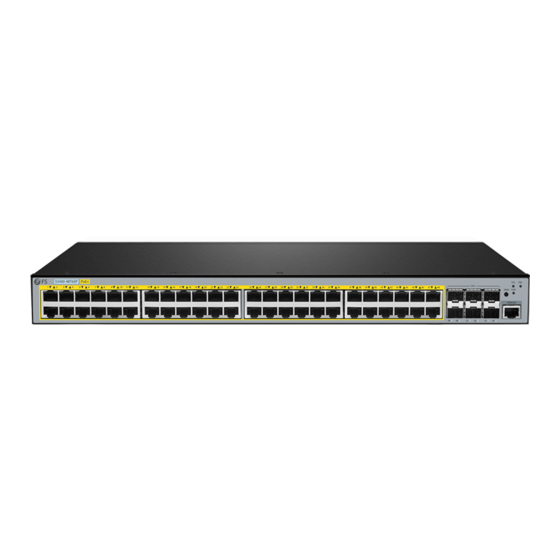
- Page 1 S3400-48T6SP Switch Hardware Installation and Maintenance Guide V1.0.2307A Innovation · Expertise · Agility...
- Page 2 Safety Statement: • To avoid harm to people and equipment, please read the safety recommendations in the Safety Precautions for FS Switches before installing the FS Switch. • Verify that the requirements described in the Safety Precautions for FS Switches have been met.
-
Page 3: Table Of Contents
Contents 1. Hardware Installation and Parts Replacement 1.1 Installation Procedure 1.2 Installation Preparation 1.3 Installing a Switch 1.4 Installing an Optical Module 1.5 Connecting a Switch 1.6 Post-Installation Checks 1.7 System Commissioning 1.8 Parts Replacement 2. Troubleshooting After Installation 2.1 Troubleshooting Flowchart 2.2 Guide to Using Optical Modules Innovation ·... -
Page 4: Hardware Installation And Parts Replacement
Hardware Installation and Parts Replacement The FS S3400-48T6SP switch provides operators with a compact, cost-effective solution for IP metro and enterprise networks. Based on high-performance hardware and FS OS platform, it supports ACL, QinQ, QoS and other functions. Its simple management mode and flexible installation can meet the needs of any complex scenario. -
Page 5: Installation Procedure
Hardware Installation and Parts Replacement Switch Hardware Installation and Maintenance Guide 1.1 Installation Procedure Installation Preparation Installing a Switch Installing Modules Connecting the Switch System Commissioning Post-Installation Checks With Cables 1.2 Installation Preparation Confirm the following before installation: • The installation site provides sufficient space for heat dissipation. •... - Page 6 Hardware Installation and Parts Replacement Switch Hardware Installation and Maintenance Guide 1.2.2 Mounting the Cabinet or Rack When mounting the cabinet, please note the following: • All expansion bolts for fastening the cabinet base to the ground should be installed and tightened in sequence from bottom to up (large flat washer, spring washer, and nut), and the installation holes on the base and the expansion bolts are aligned.
-
Page 7: Installing A Switch
Multimeter, bit error rate tester (BERT), and optical power meter Meters • The S3400-48T6SP switch is delivered without a tool kit. You need to prepare a tool kit by yourself. 1.3 Installing a Switch Precautions : Please confirm the following before installing the switch: •... - Page 8 Switch Hardware Installation and Maintenance Guide 1.3.1 Mounting the Switch in a Cabinet or Rack The S3400-48T6SP switch meets the EIA standard size and can be installed in a 19-inch wiring closet with the following installation procedure: 1: Remove the screws (packaged with the lugs) and install one end of the lugs to the switch as...
- Page 9 Hardware Installation and Parts Replacement Switch Hardware Installation and Maintenance Guide Step 1: Stick the 4 adhesive pads provided in the box in the pits at the corners of the bottom of the switch, as shown in the following figure: Step 2: Place the switch flat on the desktop to ensure good airflow ventilation around the switch as shown in the diagram below.
-
Page 10: Installing An Optical Module
Hardware Installation and Parts Replacement Switch Hardware Installation and Maintenance Guide • Pull out the dust-proof plug on the optical interface. • Please keep the dust-proof plug properly for subsequent use. • Install the optical module to the optical interface. •... - Page 11 2.Connect the other end of the AC power cable to the external AC power supply system. 1.5.2 Connecting Ethernet Cables S3400-48T6SP switch provides 48 10/100/1000Base-T ports. The port indicators correspond to the indicator lights No. 1-48, which are used to indicate the port Link/ACT status. During use, the UTP port of the switch can be led to other Ethernet terminal devices via network cables (direct or crossover).
- Page 12 Replacement Switch Hardware Installation and Maintenance Guide Since the 48 10/100/1000Base-T ports of the S3400-48T6SP switch all support the MDI/MDIX self- identification function of cables when interconnecting the S3400-48T6SP switch with other Ethernet terminals, you can use Category 5 direct-connect network cables or use Category 5 crossover network cables facilitates our practical cable selection.
- Page 13 1.5.4 Connecting the Grounding Cable There is one ground terminal on the back of the S3400-48T6SP switch chassis, which should be connected to the grounding lug of the rack first, and then connect the grounding lug to the grounding bar of the equipment room.
- Page 14 Note: The console port of the S3400-48T6SP switch does not support the flow control function, so when using Hyper Terminal to configure and manage the switch, the "Data Flow Control" should be set to "None", otherwise the problem of a single pass-through Hyper Terminal will occur.
-
Page 15: Post-Installation Checks
Hardware Installation and Parts Replacement Switch Hardware Installation and Maintenance Guide 1.6 Post-Installation Checks After the mechanical installation of the switch is completed, please perform the following checks before powering on the switch: 1.6.1 Verifying Cabinet . If the switch is installed on a cabinet, please check whether the mounting angle iron between the cabinet and the switch is firm;... - Page 16 Hardware Installation and Parts Replacement Switch Hardware Installation and Maintenance Guide Step 1: Connecting the Ethernet Cable Plug the DB-9 connector of the Ethernet cable into the serial port of the PC. Connect RJ45 connector of the Ethernet cable to the console port of the switch. Step 2: Check the Serial Port Number Open Device Manager on the computer and check the serial port number.
- Page 17 Hardware Installation and Parts Replacement Switch Hardware Installation and Maintenance Guide Step 4: Setting Terminal Parameters Parameter requirements: Baud rate is 115200, connection type is Serial, fill in COM port number according to the actual situation. The specific diagram is as follows. Figure 10: Setting Terminal Parameters Innovation ·...
-
Page 18: Parts Replacement
Hardware Installation and Parts Replacement Switch Hardware Installation and Maintenance Guide Step 5: Once the serial port parameters are set, click <Open> to enter the CLI interface 1.7.2 Powering On the Switch Checklist before Power-On . Check that the switch is fully grounded. . - Page 19 Hardware Installation and Parts Replacement Switch Hardware Installation and Maintenance Guide Procedure : Wear an ESD wrist strap or ESD gloves. When wearing an ESD wrist strap, ensure that the ESD wrist strap is in close contact with your wrist, and insert the other end into the ESD jack of the device or cabinet/rack. Before replacing an optical module, determine in which cabinet and chassis the optical module is installed, find the optical module in the chassis, and attach a label to the optical module.
- Page 20 Hardware Installation and Parts Replacement Switch Hardware Installation and Maintenance Guide Pull out the optical module, plug the dustproof plug and dispose of it. - There are two types of buckles on the optical module. A pull-rod handle that needs to be turned over to open, as shown in Figure 13.
-
Page 21: Troubleshooting After Installation
Troubleshooting After Installation Innovation · Expertise · Agility... -
Page 22: Troubleshooting Flowchart
Check the installation of the power supply module each module Check the installation of Check the LEDs on the device other modules Check serial port connection Check the cable connection and parameters Contact FS Technical Support Innovation · Expertise · Agility... -
Page 23: Guide To Using Optical Modules
115200, 8 data bits, no parity bit, 1 stop bit, and no flow control. 2.2.3 Indicator light description The LED indicators indicate the ongoing operation of the switch. The S3400-48T6SP switch indicators and their descriptions are as follows:... - Page 24 Troubleshooting After Installation Switch Hardware Installation and Maintenance Guide Number Abbreviation Meaning Description Power indicator light When the switch is powered on, this light turns on. System indicator light The indicator light is always on and the system is starting. The indicator light flashes and the system works normally.
- Page 25 FS has invested resources in product R&D, quality control, intelligent manufacturing, industry-leading experts, professional technical support, and networking solutions. All is to provide customers with higher-performance, lower-power consumption, and the most cost-effective products, promoting clients' network upgrades. For more information and technical support, welcome to contact us at www.fs.com/contact_us...
Need help?
Do you have a question about the S3400-48T6SP and is the answer not in the manual?
Questions and answers