Advertisement
Quick Links
Roll R Cover Series 3.5
INSTALLATION INSTRUCTIONS
INSTALLATION TIME: 1 hours and 45 minutes (Approximately)
IMPORTANT
Care Instructions
Maintenance
Tools Required
PERSONAL PROTECTIVE EQUIPMENT:
Chevrolet Silverado 1500 MY20+
• Do not stand/sit or rest heavy objects on Roll R Cover
• Humans or animals are not to be under the closed cover at any given time
• Tonneau Cover is not dust or water tight
• If contact with volatile chemicals occur, clean Cover with mild detergent and water solution
• Read Instructions fully before commencing installation.
• Clean Cover with a mild detergent and water solution
• Do not use abrasive cleaners or solvents
• Refer to manufactures instructions applicable to power drill.
• Protect Tub floor against scratches during installation process.
Refer to Maintenance instructions.
• Pen / Marker
• Centre Punch
• Drill & Drill bits
• Caulking Gun
• Silicon - Non Acetic
Issue 1 12/02/24
WWW.HSPUTELIDS.COM
Part No: CS4R-S3.5
• Scissors & Knife
• Spanner & Socket
• Tape measure
• Holesaw
• Filing tool
Rubber Gloves
Goggles
• Soapy water solution
• Allen Key set
• Screw driver
• Rust Inhibitor
• Trim Removal Tool
Hearing Protection
Page 1 of 22
Advertisement

Related Manuals for HSP CS4R-S3.5


Summary of Contents for HSP CS4R-S3.5
- Page 1 Roll R Cover Series 3.5 WWW.HSPUTELIDS.COM Part No: CS4R-S3.5 INSTALLATION INSTRUCTIONS Chevrolet Silverado 1500 MY20+ INSTALLATION TIME: 1 hours and 45 minutes (Approximately) • Do not stand/sit or rest heavy objects on Roll R Cover • Humans or animals are not to be under the closed cover at any given time •...
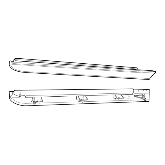
- Page 2 BOX CONTENTS LEFT & RIGHT SIDE RAIL CANISTER ASSEMBLY S2.5-DC-AE-002ps-CS4R S2.5-DC-AE-003ds-CS4R S3-XC-AF-001/002_CS4 CANISTER TOP COVER S2.5-DC-AE-005 -CS4 SPECIFIC KIT CS4R COVER END CAPS S2.5-DC-PI-004ps BATTERY Drainage pipe CS4-RB CABLE TIE COUNTERSUNK LOOM S2.75 Qty - 2 Qty x 16 Qty - 2 SCREW Qty - 4 S2.5-DC-PI-004ds M8 SPRING...
- Page 3 Clean are as indicated. Measure down from top of headboard 270mm & 110mm from inside wall of bed as shown. Repeat to the other side. Using a 30mm hole-saw drill through tub front panel, file away any sharp edges. Apply anti rust coating.
- Page 4 Remove and retain tail lights. In the specified orientation insert the rear drainage pipe into the factory hole. Leaving 150mm hanging of the pipe hanging out. Check the tail light cavity to ensure there are no obstructions to the drainage pipe. Repeat to the other side. Re-fit the tail lights.
- Page 5 1. Apply 3m primer to the top of head board as indicated. 2. Run foam seal provided along the front ( inside edge towards tailgate) of the tub to make head-rail level with sides. Foam seal Seal any exposed gaps or holes on the front panel of the Ute bed with sealant. Install front drain pipes ( 55mm diameter end of hose) through pre-drilled holes on the front tub panel.
- Page 6 1. As indicated measure down from plastic trim by 3mm and mark. 2. Position the top of the bracket (CS4-RB) so that it aligns with the previously marked line and the side of the bracket should be aligned just before the indicated curve of the side wall of the ute tub. Measure down from plastic trim by 3mm and mark.
- Page 7 Disconnect fuse patch from battery loom S2.75. Wiring Harness steps Locate the front left grommet on the side wall of the tub, remove grommet and feed battery loom through the hole. Battery Loom S2.75 Run the wiring from the front of tub side wall ( leaving 200mm in the tub) to the battery over the chassis rail. Making sure to keep away from hot obstructions and cable tie every 400mm.
- Page 8 Run wiring from front tub corner cavity to drivers side kick panel. Cable tie wiring every 500mm over chassis rail. Find the large grommet on the firewall, make a small incision & run the loom through it to enter the cab and towards the kick panel. Seal accordingly. Note: If no grommet is visible on th firewall, you may find any access to the kick panel, seal accordingly where required.
- Page 9 Disconnect the beige indicated plug. ATTENTION: This step is for MY23+ Using CS-PATCH (MY20-MY22) or CS-1-PATCH to MY23+ connect to the vehicle harness. Plug CL-LOOM-LONG to CS-PATCH wiring. NOTE: image used is for illustration purpose only. Page 9 of 22...
- Page 10 keep the cannister in the foam blocks from the packaging for assembly. With assistance turn the canister on its back on the foam blocks. Disengage motor from the axle by unfastening Remove and retain the 3 screw the 3 Screws as indicated. Retain all parts. from the canister as indicated.
- Page 11 Important Note: Ensure that the Z seal within the track is positioned over the curtain ✓ and not folded inward. WARRANTY voided if CAUTION assembled incorrectly. ALIGN CAREFULLY Align side rail to side of canister, guide the track to go in between the curtain end rubber stop.
- Page 12 1. Using the retained screws, spring washer and washer, Loosely fasten the side rail to the location indicated. 2. Side rail edge must compress and meet with the canister profile as indicated below. 3. Fasten all screws tight. Connect motor connector to receiver Connect LED Loom to receiver Page 12 of 22...
- Page 13 Important Note: Ensure that the Z seal within the track is positioned over the curtain and not folded inward. WARRANTY voided if assembled incorrectly. ✓ CAUTION ALIGN CAREFULLY Align side rail to side of canister, guide the track to go in between the curtain end rubber stop. NOTE: LHS side rail to be assembled first.
- Page 14 1. Using the retained screws, spring washer and washer, Loosely fasten the side rail to the location indicated. 2. Side rail edge must compress and meet with the canister profile as indicated below. 3. Fasten all screws tight. Feed M6 bolt through spring washer, motor and rubber bush. NOTE: Rubber bush orientation has to be as per image.
- Page 15 Fasten all 3 screws to 2nm torque. Over tensioning will cause operating issue's. Motor is to sit level. Any obstructions between motor and canister may cause operating issues. Apply D-sponge foam tape to side rail as indicated. NOTE: Join foam firmly to the per-fitted foam of the canister.
- Page 16 Carefully bring down the assembled unit. Insert side end caps to the top cover. Place & Align top cover over the Using countersunk screws provided, line up end cap canister and side rails. holes to the threads on the side rail. Fasten to 3nm torque.
- Page 17 Place the Roll-R-Cover unit on to Ute bed. 4 People Recommended for lift With care, pull out any side rubber that has folded under the side rail. LHS & RHS Page 17 of 22...
- Page 18 To the locations indicated below position clamp behind the inner top lip of the bed rail and the center elongated hole of the side rail mounting brackets. Repeat to other side. Fasten clamp loosely into position using M8 washer, M8 spring washer and Ensure the M8 nut is in M8 x 35mm bolt.
- Page 19 As indicated loosely attach the side rail's bracket to the tub bracket using supplied M8 washer, M8 spring washer, and an M8 x 16mm button head bolt." With the tailgate up (Closed position), Pull left & right hand side rails towards the tailgate, stopping short by 5mm between tailgate and side-rail end-cap.
- Page 20 Please follow the steps in order starting with point 1. 1. Apply downward pressure on side rails. 2. Lift clamp all the way up or as far up as possible then fasten clamp to 14Nm torque in the order indicated below. Clamp Clamp Clamp...
- Page 21 Install front drain pipes through pre-drilled holes of the canister. ( RHS/LHS) Note: With care push tube in. Gently pull the tube back so it seals correctly against the front panel of the tub. Note: With care push rear pipe in. Gently pull the pipe back so it seals correctly within the side rail channel.
- Page 22 a. Connect Battery loom S2.75 to Receiver loom. b. Carefully connect S3-CL-PATCH to Receiver loom. Align connectors carefully to avoid pushing pins out. Carefully connect Cl-Loom-Long tos3-cl-patch. Align connectors carefully to avoid pushing pins out. Operating instructions: Press unlock on vehicle key fob to activate controller.
Need help?
Do you have a question about the CS4R-S3.5 and is the answer not in the manual?
Questions and answers