urmet domus U1 User Manual
Voice call module
Hide thumbs
Also See for U1:
- User manual (44 pages) ,
- Quick start manual (12 pages) ,
- Installation manual (4 pages)

Related Manuals for urmet domus U1


Summary of Contents for urmet domus U1
- Page 1 USER MANUAL U1 Voice Call Module Sch./Ref. 1036/16 Version: V1.4 Code: SRD-UME1036/16-1113-V1.4...
- Page 2 Preface Thank you for choosing Urmet product. This manual is the user manual of U1 series digital system U1 Voice Call Module (Ref. 1036/16). Please read this manual carefully before using the U1 Voice Call Module. Disclaimer Although all contents in this manual have been checked carefully, biases and errors may exist in it.
-
Page 3: Table Of Contents
IS IN YOUR LIFE Table of Contents Chapter 1 Product overview ................1 1.1 Function characteristics ................1 1.2 Specifications ..................... 1 1.2.1 Working parameters ............... 1 1.2.2 Camera .................... 1 1.2.3 Display screen ................. 2 1.2.4 Product dimension ................2 1.3 Description of appearance and interface .......... - Page 4 IS IN YOUR LIFE Notes ......................29 Appendix Figure index ................. 30...
-
Page 5: Chapter 1 Product Overview
This product is a major equipment of digital building intercom system. It adopts standard Category 5 cable connection to achieve communication with U1 Voice 7” IP Monitor or U1 Voice Switch Board, and supports IC access control. 1.1 Function characteristics 4.3-inch TFT display screen... -
Page 6: Display Screen
IS IN YOUR LIFE Fill light mode: white light Minimum illumination: 0 lux 1.2.3 Display screen Size: 4.3” Type: LCD Resolution: 480× 272 1.2.4 Product dimension W * H * D: 148.5 * 363 * 47 mm... -
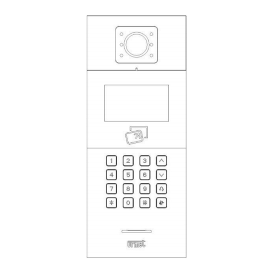
Page 7: Description Of Appearance And Interface
IS IN YOUR LIFE 1.3 Description of appearance and interface 1.3.1 Front view Figure1. 1 Front view Aluminum panel Lens light Fill light Display area Card swiping area Keypad area Loudspeaker... -
Page 8: Rear View
1.3.2 Rear view Figure1. 2 Rear view Number ①: +12V: Only when the input voltage of the U1 Voice Call Module is >18V can it provide +12V voltage. When +12V input voltage is adopted, the output voltage will be lower than +10V (Non-PoE power supply mode). - Page 9 IS IN YOUR LIFE COM NO NC: The common end, normally open end and normally closed end of the unlock relay. GS: Input end for door status detection. UNLOCK GND: Inside unlock activation/deactivation input.
-
Page 10: Chapter 2 Operating Instructions
IS IN YOUR LIFE Chapter 2 Operating instructions 2.1 Call the resident Standard dialing: visitor may initiate a call by entering the room number of the resident (such as 0101). This phone is provided with the ring back tone function. The visitor may cancel the call by pressing the * key when it is ringing. The call shall end automatically if the resident doesn't respond within 30 seconds. - Page 11 (1-99) + unit number (1~9) + room number, such as 011+0101. In short code mode, visitor enters the unit number (1~999) + room number (1~999). Figure2. 1 U1 Voice dialing interface Figure2. 2 U1 Voice dialing interface (short code)
- Page 12 IS IN YOUR LIFE Figure2. 3 MCM dialing interface Figure2. 4 MCM residents list interface...
-
Page 13: Call The Management Center
Figure2. 5 MCM residents list search interface 2.2 Call the management center The visitor can call the management center of the community by pressing the key on the U1 Voice Call Module when it is in standby mode. 2.3 Unlock Unlock via card swiping Unlock by pressing the registered card close to the card swiping area on the U1 Voice Call Module. - Page 14 IS IN YOUR LIFE method to activate password unlock function. Initial common password is 999999.
-
Page 15: Chapter 3 Enter Into The Setting Interface
IS IN YOUR LIFE Chapter 3 Enter into the setting interface Figure3. 1 Standby interface At standby interface, press "#" key and then press " * " key to enter into engineering setting login interface. The default engineering setting password is "000000". Figure3. - Page 16 IS IN YOUR LIFE engineering setting interface; press the up/down key or corresponding numeric key on the icon to enter into corresponding menu. Figure3. 3 Main engineering setting interface...
-
Page 17: Chapter 4 System Setting
IS IN YOUR LIFE Chapter 4 System setting The system setting interface is shown in the figure below. It includes time setting, sound setting, language setting, password setting, unlock time setting, access control card management and elevator linkage. Press the up/down key or corresponding numeric key on the icon to enter into corresponding menu. -
Page 18: Sound Setting
IS IN YOUR LIFE Figure4. 2 Time setting interface 4.2 Sound setting The sound setting interface is shown in the figure below. Press the up/down key or numeric key to select corresponding option and press "#" key to adjust it. After adjustment, press "*"... -
Page 19: Password Setting
IS IN YOUR LIFE confirming the setting by pressing "#" key. Figure4. 4 Language setting interface 4.4 Password setting password setting interface divided into user password activation/deactivation, common password activation/deactivation common password modification. Press the up/down key or corresponding numeric key on the icon for adjustment or setting. Figure4. -
Page 20: Unlock Duration Setting
IS IN YOUR LIFE 4.5 Unlock duration setting The unlock duration setting is used to set the duration that the door remains open. The door will be closed automatically when the duration expires. Press the numeric key to enter the desired time (in seconds), press "*" key to delete the content, or press "#"... - Page 21 IS IN YOUR LIFE Figure4. 7 Access control card management interface At REGISTER interface, complete the registration by swiping the card or entering the card number directly. After registration, press "#" key to confirm the registration or press "*" key to return to the previous menu. If a wrong number is entered in the process of card number entering, delete the entered numbers one by one by pressing "*"...
- Page 22 "*" key to return. The COPY CARD DATA function can copy the card number information of this phone to other U1 Voice Call Modules or MCMs. After entering into the interface, first press the up/down key to select target phone type, then press "#"...
-
Page 23: Elevator Linkage
IS IN YOUR LIFE Figure4. 10 COPY CARD DATA interface 4.7 Elevator linkage Elevator linkage defaults to be deactivated. It may be set as activated or deactivated as needed. Figure4. 11 Elevator linkage interface... -
Page 24: Chapter 5 Engineering Setting
IS IN YOUR LIFE Chapter 5 Engineering setting The engineering setting interface is shown in the figure below. It includes equipment property, dial setting, alarm setting, factory test, engineering password, company information and equipment information. Press the up/down key or corresponding numeric key on the icon to enter into corresponding setting interface. - Page 25 IS IN YOUR LIFE After entering into the submenu, U1 Voice Call Module number is divided into building number (1-99), unit number (1-9) and serial number (1-32). Figure5. 3 U1 Voice Call Module number setting interface MCM only has serial number 1-32.
-
Page 26: Dial Setting
Dial setting interface display varies with equipment type. When the equipment type is U1 Voice Call Module, the dial setting interface shall be as follows: For 3 dial digits, auto dial can be carried out by pressing 3 numbers at the dial interface, e.g., 818 represents Room 18, F/8. -
Page 27: Alarm Setting
When the equipment type is MCM, the dial setting interface shall be as follows. Unit dial digit can be 1, 2 or 3 digits, and U1 Voice 7” IP Monitor dial digit can be 3 or 4 digits. See the MCM dial rule table for corresponding configured call. - Page 28 IS IN YOUR LIFE Figure5. 7 Alarm setting interface Factory test interface includes various test items, among which the test items that the project contractor may use are system reboot and restoring factory setting. When clicking the SYSTEM REBOOT key, a dialog box will pop up; system reboot will be executed after selecting the CONFIRM key.
-
Page 29: Engineering Password Modification
IS IN YOUR LIFE Attention: All data will be cleared if restoring factory setting operation is executed within 30 seconds after power on. 5.4 Engineering password modification The engineering modification interface is shown in the figure below: First enter the old password. When the correct old password is entered, the cursor will jump to the new password field automatically, now enter the new password. - Page 30 IS IN YOUR LIFE Figure5. 10 Equipment information interface...
-
Page 31: Chapter 6 Installation
IS IN YOUR LIFE Chapter 6 Installation 6.1 Installation steps First step: Place the embedded box in the reserved slot on the wall. After passing the wiring terminal through the outlet, fix firmly Wall nails with nails or enclose and fix with cement near Embedded Reserved the embedded box. -
Page 32: Recommended Installation Height
IS IN YOUR LIFE 6.2 Recommended installation height Ground U1 Voice Call Module:the top of the product is 1.64 meters above the ground. Embedded Box:the top of the product is 1.63 meters above the ground. Notices during installation: 1) When forming square groove on the lower cover of the equipment, attention shall be paid to the control of embedding depth, and the 4 openings on the lower cover must adhere to the wall firmly. - Page 33 IS IN YOUR LIFE Notes 1. Please keep the equipment away from strong magnetic field, hot and moist environments; Be away from Be away from Be away from magnetic field hot environment moisture 2. Protect the equipment from falling down on the ground or being subject to high impact;...
- Page 34 Figure5. 1 Engineering setting interface ............20 Figure5. 2 Equipment property setting interface ..........20 Figure5. 3 U1 Voice Call Module number setting interface ......21 Figure5. 4 MCM number setting interface ............22 Figure5. 5 Door dial setting interface .............. 22 Figure5.
Need help?
Do you have a question about the U1 and is the answer not in the manual?
Questions and answers