
Related Manuals for Metrologic MK3780-31A62


Summary of Contents for Metrologic MK3780-31A62
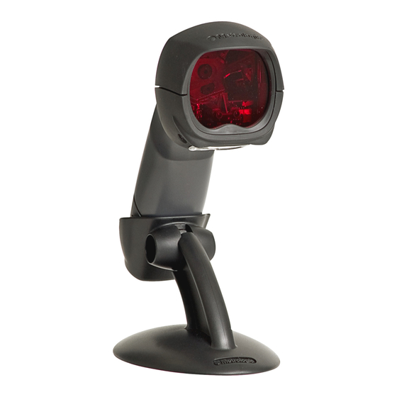
- Page 1 METROLOGIC INSTRUMENTS, INC. ® MS3780 Fusion Omni/Single Line Scanner Installation and User’s Guide...
- Page 2 Copyright © 2008 by Metrologic Instruments, Inc. All rights reserved. No part of this work may be reproduced, transmitted, or stored in any form or by any means without prior written consent, except by reviewer, who may quote brief passages in a review, or provided for in the Copyright Act of 1976.
-
Page 3: Table Of Contents
Full Speed or Low Speed USB (Integrated) ........... 11 EAS Deactivation ................... 12 Scanner Operation The Scan Pattern Mode Select Button ............13 How to Use CodeGate and the Manual Activation Mode ....... 14 Indicators Audible ....................... 15 Visual ......................16 Failure ...................... - Page 4 ABLE OF ONTENTS Troubleshooting Guide ..................23 Design Specifications ..................27 Applications and Protocols ................. 29 Default Settings - Communication Parameters........... 30 Configuration Modes ..................35 Bar Codes ....................35 MetroSet2....................35 Serial Configuration ..................35 Upgrading the Firmware ................. 36 Scanner and Cable Terminations ...............
-
Page 5: Introduction Product Overview
It utilizes the powerful Metrologic ® QuantumE scan engine to provide an outstanding scan performance on all standard 1D bar code symbologies, including RSS. Designed for retail applications, the Fusion includes additional key product features like: •... -
Page 6: Scanner And Accessories
Metrologic Voltage Converter Cable, ±12VDC to +5.2VDC MVC-3MPC-IB9 For IBM Applications Other items may be ordered for the specific protocol being used. To order additional items, contact the dealer, distributor or call Metrologic’s customer service department at 1-800-436-3876... - Page 7 55-55809x-N-E-3 Long strain relief, straight cable, black 46-00225 Stand Other items may be ordered for the specific protocol being used. To order additional items, contact the dealer, distributor or call Metrologic’s customer service department at 1-800-436-3876. ® Applicable for IBM...
-
Page 8: Scanner Components
Red Output Window, Laser Aperture (See page 41) Mode Select Button (See page 13) Beeper (See page 15) Blue LED, Single-Line Mode / Menu Reading (See page 15) White LED (See page 15) Blue LED, All Scan Lines On / Omnidirectional Reading (See page 15) -
Page 9: Caution And Serial Number Labels
Figure 2. Caution and Serial Labels Caution: To maintain compliance with applicable standards, all circuits connected to the scanner must meet the requirements for SELV (Safety Extra Low Voltage) according to EN/IEC 60950-1. To maintain compliance with standard CSA C22.2 No. 60950-1/UL 60950-1 and norm EN/IEC 60950-1, the power source should meet applicable performance requirements for a limited power source. -
Page 10: Cable Removal
When cleaning the window, spray the cleaner onto a lint free, non- abrasive cleaning cloth then gently wipe the window clean. If the unit's case requires cleaning, use a mild cleaning agent that does not contain strong oxidizing chemicals. Strong cleaning agents may discolor or damage the unit's exterior. -
Page 11: Installation
When the scanner first receives power the white LED will flash, one blue LED will turn on and the scanner will emit one beep. Plugging the scanner into the serial port of the PC does not guarantee that scanned information will appear at the PC. A software driver and correct configuration setting are also required for proper communication to occur. -
Page 12: Rs485 Or Ocia
When the scanner first receives power the white LED will flash, one blue LED will turn on and the scanner will emit one beep. Plugging the scanner into the serial port of the PC does not guarantee that scanned information will appear at the PC. A software driver and correct configuration setting are also required for proper communication to occur. -
Page 13: Keyboard Wedge
Connect AC power to the transformer. Turn on the host device. When the scanner first receives power the white LED will flash, one blue LED will turn on and the scanner will emit one beep. Powering the MS3780 directly from the host device can sometimes cause interference with the operation of the scanner or the computer. -
Page 14: Stand-Alone Keyboard Wedge
Turn on the host device. When the scanner first receives power the white LED will flash, one blue LED will turn on and the scanner will emit one beep. Powering the MS3780 directly from the host device can sometimes cause interference with the operation of the scanner or the computer. -
Page 15: Full Speed Or Low Speed Usb (Integrated)
When the scanner first receives power the white LED will flash, one blue LED will turn on and the scanner will emit one beep. Plugging the scanner into the USB port of the PC does not guarantee that scanned information will appear at the PC. A software driver and correct configuration setting are also required for proper communication to occur. -
Page 16: Eas Deactivation
NSTALLATION EAS Deactivation SW1 and SW2 are the switch banks inside the Checkpoint Device that set the deactivation range. The following is a list of Checkpoint recommended switch bank settings. Checkpoint Recommended Switch Bank Settings For RS232 and IBM Switch 1 and 6... -
Page 17: Scanner Operation
There are two configurable scan pattern modes available with the MS3780. • The primary scan pattern mode is the default scan pattern active when the scanner starts. By default, the primary scan pattern is set to all-scan-lines for omnidirectional reading. -
Page 18: How To Use Codegate And The Manual Activation Mode
Mode. Figure 16. Figure 17. Factory Defaults: In-Stand, CodeGate is not active (Amber LED is On) Out-of-Stand, CodeGate is active (Amber LED is Off) For information on how to change the factory defaults, refer to the MetroSelect Configuration Guide (00-02407). -
Page 19: Audible Indicators
When the scanner first receives power; the white LED will flash, one blue LED will turn on and the scanner will emit a beep (the white LED will remain on for the duration of the beep). The scanner is now ready to scan. -
Page 20: Visual
CANNER PERATION Visual Indicators There are four LEDs located on the top of the MS3780. When the scanner is on, the flashing or constant illumination of the LEDs indicates the status of the current scan and the scanner. Figure 18. LED Indicators... -
Page 21: Failure
Return the unit to a Metrologic authorized service center for repair. Three Beeps - On Power Up This indicates that the nonvolatile memory that holds the scanner configuration has failed. Return the unit to a Metrologic authorized service center for repair. -
Page 22: Depth Of Field Specifications
CANNER PERATION Depth of Field Specifications* Normal Scan Zone Specifications are based on a 0.33 mm (13 mil) bar code. Figure 19. Normal Depth of Field * All specifications are subject to change without notice. -
Page 23: Reduced Scan Zone
CANNER PERATION Depth of Field Specifications* Reduced Scan Zone Specifications are based on a 0.33 mm (13 mil) bar code. Figure 20. Reduced Depth of Field * All specifications are subject to change without notice. -
Page 24: Depth Of Field By Bar Code Element Width
CANNER PERATION Depth of Field by Bar Code Element Width* Normal Scan Zone INIMUM LEMENT IDTH mils Figure 21. Normal Scan Zone by Bar Code Element Width * All specifications are subject to change without notice. -
Page 25: Reduced Scan Zone
CANNER PERATION Depth of Field by Bar Code Element Width* Reduced Scan Zone INIMUM LEMENT IDTH mils Figure 22. Reduced Scan Zone by Bar Code Element Width * All specifications are subject to change without notice. -
Page 26: Ir Activation Range
The motor will turn off after twenty-five minutes of non-use. Any movement detected by the IR in the activation area will cause the scanner to exit power save mode. The laser and motor will automatically turn back on preparing the scanner for bar code recognition, decoding and transmission. -
Page 27: Troubleshooting Guide
ROUBLESHOOTING UIDE The following guide is for reference purposes only. Contact a Metrologic representative at 1-800-ID-METRO or 1-800-436-3876 to preserve the limited warranty terms on page 44. Symptoms Possible Cause(s) Solution All Interfaces Check the transformer, outlet The unit has no No power is being and power strip. - Page 28 ROUBLESHOOTING UIDE Symptoms Possible Cause(s) Solution All Interfaces The unit scans If the scanner is setup to support The scanner is a bar code, but ACK/NAK, RTS/CTS, configured to support locks up after XON/XOFF or D/E, verify that some form of host...
- Page 29 The unit powers properly. up OK and Check to make sure that the scans OK but baud rate and parity of the The cable is not does not scanner and the communication...
- Page 30 Make sure that the proper PC type (ie. AT, PS2 or XT) is selected. The unit scans The unit may not be but the data is Verify correct country code and configured correctly.
-
Page 31: Design Specifications
All standard 1-D bar codes including RSS-14, Decode Capability: RSS-Expanded, and RSS-14 Limited RS232, Keyboard Wedge, Stand-Alone Keyboard, Light Pen System Interfaces: Emulation, RS485, USB (low speed and full speed), OCIA Print Contrast: 35% minimum reflectance difference Up to 80 data characters No. Characters Read: Maximum number will vary based on symbology and density. - Page 32 275 mA typical at 5VDC Standby Current: 200 mA typical at 5VDC DC Transformers: Class II; 5.2VDC @ 1A For regulatory compliance information, see pages 41 - 43. Environmental Operating Temperature: -20°C to 40°C (-4°F to 104°F) Storage Temperature: -40°C to 60°C (-40°F to 140°F)
-
Page 33: Applications And Protocols
United Kingdom • • Hungarian Spanish Default setting. For a complete list of default settings, see Default Settings - Communication Parameters starting on page 30 of this guide. Refer to the ® MetroSelect Configuration Guide ( 00-02407) or MetroSet2’s help files MLPN for information on how to change the default settings. -
Page 34: Default Settings - Communication Parameters
The scanner is shipped from the factory configured to a set of default conditions. The default parameter of the scanner has an asterisk ( * ) in the charts on the following pages. If an asterisk is not in the default column then the default setting is off or disabled. - Page 35 RS485 ARAMETER EFAULT Expanded ID “]e0” RSS Limited Enable RSS Limited ID “]e0” RSS Limited App ID “01” RSS Limited Check Digit Bars High as Code 39 Spaces High as Code 39 Bars High as Scanned Spaces High as Scanned...
- Page 36 Convert EAN-8 to EAN-13 Transmit UPC-A Number System Transmit UPC-A Manufacturer Transmit UPC-A Item ID# Transmit Codabar Start/Stop Characters CLSI Editing (Enable) Transmit Mod 43 Check Digit on Code 39 Transmit Code 39 Stop/Start Characters Transmit Mod 10/ITF Transmit MSI-Plessey Check Characters Parity...
- Page 37 LRC Enabled UPC Prefix UPC Suffix Transmit AIM ID Characters STX Prefix ETX Suffix Carriage Return Line Feed - disabled by default in KBW Tab Prefix Tab Suffix “DE” Disable Command “FL” Laser Enable Command DTR Handshaking Support RTS/CTS Handshaking...
- Page 38 OCIA RS232* RS485 ARAMETER EFAULT Supplements are not Required Two Digit Redundancy Five Digit Redundancy 100 msec to Find Supplement Configurable in 100msec steps (MAX 800 msec) as code 39 Coupon Code 128 Configurable Code Lengths avail. Configurable Prefix Characters avail.
-
Page 39: Configuration Modes
Serial Configuration This mode of configuration is ideal for OEM applications. This mode gives the end-user the ability to send a series of commands using the serial port of the host system. The commands are equivalent to the numerical values of the bar codes located in the MetroSelect Single-Line Configuration Guide 00-02544). -
Page 40: Upgrading The Firmware
MetroSet2 software . A personal computer running Windows 95 or greater with an available RS232 serial or USB port is also required to complete the upgrade. PowerLink Cable #54-54014 is required when using RS232 for the upgrade process. This cable can be ordered from Metrologic at 1-800-ID-METRO. -
Page 41: Scanner And Cable Terminations
CANNER AND ABLE ERMINATIONS Scanner Pinout Connections The MS3780 scanner interfaces terminate to a 10-pin modular socket. The serial number label indicates the interface enabled when the scanner is shipped from the factory. Figure 24. MS3780-47 MS3780-41 Keyboard Wedge and... - Page 42 Clock Out Clock in Return/ IBM A+ Receive Clock out Rtrn +5VDC +5VDC Shield Ground Shield Ground MS3780-120 USB and RS232 with EAS Function Ground RS232 Transmit Output RS232 Receive Input EAS - EAS + USB D+ USB +V USB D-...
- Page 43 CANNER AND ABLE ERMINATIONS Cable Connector Configurations (Host End) RS232 PowerLink Cable 53-53000x-3 Function Shield Ground RS232 Transmit Output RS232 Receive Input DTR Input/Light Pen Source Power/Signal Ground Light Pen Data CTS Input 9-Pin D-Type Connector RTS Output +5VDC USB Power/Communication Cable...
- Page 44 PC Clock No Connect Metrologic will supply an adapter cable with a 5-pin DIN male connector on one end and a 6-pin mini DIN female connector on the other. According to the termination required, connect the appropriate end of the adapter cable to the PowerLink cable, leaving the necessary termination exposed for connecting to the keyboard and the keyboard port on the PC.
-
Page 45: Regulatory Compliance
Never attempt to look at the laser beam, even if the scanner appears to be nonfunctional. Never open the scanner in an attempt to look into the device. Doing so could result in hazardous laser light exposure. The use of optical instruments with the laser equipment will increase eye hazard. - Page 46 Folgendes trifft zu, wenn das Scannerkabel länger als 3 Meter ist: This equipment has been tested and found to comply with limits for a Class A digital device, pursuant to part 15 of the FCC Rules. These limits are designed to provide reasonable protection against harmful interference when the equipment is operated in a commercial environment.
- Page 47 If this equipment does cause harmful interference to radio or television reception, which can be determined by turning the equipment off and on, the user is encouraged to try to correct the interference by one or more of the following measures: •...
-
Page 48: Limited Warranty
Federal, state and local laws, regulations and ordinances pertaining to their production and labeling. This warranty is limited to repair, replacement of product or refund of product price at the sole discretion of Metrologic. Faulty equipment must be returned to one of the following Metrologic repair facilities: Blackwood, New Jersey, USA;... -
Page 49: Patents
ATENTS Patent Information This METROLOGIC product may be covered by, but not limited to, one or more of the following U.S. Patents: U.S. Patent No.; 5,216,232; 5,260,553; 5,340,971; 5,340,973; 5,424,525; 5,468,951; 5,484,992; 5,525,789; 5,528,024; 5,557,093; 5,591,953; 5,616,908; 5,627,359; 5,637,852; 5,661,292; 5,767,501; 5,777,315; 5,789,730;... -
Page 50: Indicators Audible
Accessories .......2, 3 EMC..........42 Adapter..........9 EMI ..........42 Audible Indicator.. 15–17, 23–26, 36 Emissions........42 Bar Code ..15–17, 23–26, 27, 35 Failure Bar Width........27 Modes........17 Beep ....15, 16, 17, 23–26, 36 Firmware ........36 Blue LED ....15–17, 23–26 Flash ROM........ - Page 51 USB ........ 11, 30–34 Port......7–11, 23–26 Power ......2, 7–11, 36 Power Supply ........6 Ventilation ........28 PowerLink........7–11 Visual Indicator ... 15–17, 23–26, 36 Protocol ........29 Amber LED....4, 23–26 Blue LED ....... 4, 23–26 White LED ..... 4, 23–26 RAM ..........25 Voltage......
- Page 53 OTES...
- Page 54 OTES...
- Page 56 March 2008 Printed in the USA 0 0 - 0 2 2 6 9 E...
Need help?
Do you have a question about the MK3780-31A62 and is the answer not in the manual?
Questions and answers