
Related Manuals for Metrologic MK9520-37A38


Summary of Contents for Metrologic MK9520-37A38
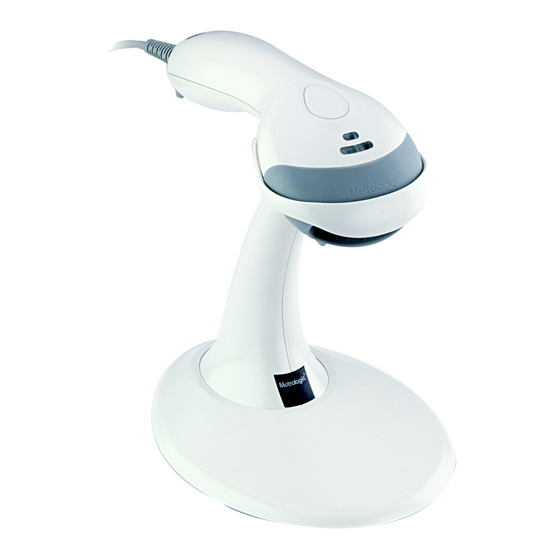
- Page 1 METROLOGIC INSTRUMENTS, INC. MS9500 Voyager Series ® Single-Line Hand Held Laser Scanner Installation and User's Guide...
- Page 2 Copyright © 2008 by Metrologic Instruments, Inc. All rights reserved. No part of this work may be reproduced, transmitted, or stored in any form or by any means without prior written consent, except by reviewer, who may quote brief passages in a review, or provided for in the Copyright Act of 1976.
-
Page 3: Table Of Contents
Disconnecting....................5 Connecting ....................5 Labels....................... 6 Maintenance..................... 6 Installing the Scanner to the Host System RS232, Laser Emulation, and Light Pen Emulation.......... 7 RS485 ......................8 Keyboard Wedge....................9 Stand-Alone Keyboard ................... 10 Integrated USB Full Speed ....................11 Low Speed .................... - Page 4 Default Settings ....................33 Scanner and Cable Terminations Scanner Pinout Connections ................38 Cable Connector Configurations ..............40 Limited Warranty ....................42 Regulatory Compliance Safety ......................43 EMC ....................... 44 Patents ....................... 46 Index ........................47 Contact Information and Office Locations............49...
-
Page 5: Product Overview
The user can then press the CodeGate button, to transmit the data to the host system. When the MS9540 is placed in the stand the CodeGate button feature will automatically deactivating for hands free operation. -
Page 6: Scanner And Accessories
Stand Alone Keyboard Wedge PowerLink Cable 53-53020x-3 Black, Coiled cord, with Long Strain Relief Other items may be ordered for the specific protocol being used. To order additional items, contact the dealer, distributor or call Metrologic’s Customer Service Department at 1-800-ID-METRO or 1-800-436-3876. - Page 7 Hard Mount Accessory Kit (used with kit #46-46128) 46-46508 Wall Mount Hanger Accessory Kit Other items may be ordered for the specific protocol being used. To order additional items, contact the dealer, distributor or call Metrologic’s Customer Service Department at 1-800-ID-METRO or 1-800-436-3876.
-
Page 8: Scanner Components
See Scanner Pinout Connections on page 38 Figure 1. Scanner Components ♦ In some custom units the standard green LED has been replaced with a blue LED and the red LED has been replaced with a white LED. ♦♦ Items are provided with the MS9540, VoyagerCG model only. -
Page 9: Disconnecting
PowerLink cable. Figure 2. Locate the small ‘pin-hole’ on the top of the unit near the bottom of the Voyager logo. Bend an ordinary paperclip into the shape shown above. -
Page 10: Labels
NTRODUCTION Labels Every scanner has labels and molded text located on the underside of the unit. The labels and text contain important information such as the unit’s date of manufacture, serial number, CE and caution information. Figure 5 provides examples of the labels and the molded text. -
Page 11: Installing The Scanner To The Host System
Figure 6. Turn on the host system. Plugging the scanner into a port on the host system does not guarantee that scanned information will be communicated properly to the host system. Please refer to the MetroSelect Single-Line Configuration Guide or MetroSet2’s help files for instructions on changing the... -
Page 12: Rs485
Turn on the host system. Figure 7. Plugging the scanner into a port on the host system does not guarantee that scanned information will be communicated properly to the host system. Please refer to the MetroSelect Single-Line Configuration Guide or MetroSet2’s help files for instructions on changing the... -
Page 13: Keyboard Wedge
DIN adapter). Power up the host system. Plugging the scanner into a port on the host system does not guarantee that scanned information will be communicated properly to the host system. Please refer to the MetroSelect Single-Line Configuration Guide or MetroSet2’s help files for instructions on changing the scanner’s factory default configuration. -
Page 14: Stand-Alone Keyboard
Contact a Metrologic Customer Service Representative if you require an external power supply. Plugging the scanner into a port on the host system does not guarantee that scanned information will be communicated properly to the host system. Please refer to the MetroSelect Single-Line Configuration Guide or MetroSet2’s help files... -
Page 15: Integrated Usb Full Speed
Single-Line Configuration Guide ( 00-02544). MLPN Plugging the scanner into a port on the host system does not guarantee that scanned information will be communicated properly to the host system. Please refer to the MetroSelect Single-Line Configuration Guide or MetroSet2’s help files for instructions on changing the scanner’s factory default configuration. -
Page 16: The Ms9540 Voyagercg ® Series
• CodeGate activates when removed from the stand • Bar code data is transmitted when the button is pressed Manual Activation Mode*, Out-of-Stand • Button activates laser • Bar code data is scanned and transmitted while button is held down... -
Page 17: Stand Kits
Kit Contains: a. Wall Mount Hanger ........Qty. 1 b. Wall Mount Base ........Qty. 1 c. 4.8 x 13 mm, Self Tapping Screw ....Qty. 2 d. Double-Sided Adhesive Tape ....Qty. 1 e. #8 Wood Screw.......... Qty. 2... -
Page 18: Assembly
TAND Assembly There are two options for assembling the stand. The first option is a self- supporting stand that can be moved freely about on the countertop. The second option is used if the stand will be bolted or hard-mounted to the countertop. - Page 19 Kit #46-46351 or MS951 Stand Base Figure 21. Step 4 Remove the logo plate on the stand by gently using an exacto knife to release the plate hook. Figure 22. Step 5 Position the stand over the base assembly.
- Page 20 Wall Mount, Option 1: For Kit #46-46508 Step 1 Drill two #39 pilot holes 3.00″ apart. Step 2 Attach the Wall Mount Hanger to the wall with the two #8 wood screws provided. Figure 26. Wall Mount, Option 2: Kit #46-46508...
-
Page 21: Indicators
When in configuration mode, a short razzberry tone will sound if an invalid bar code is scanned. In some custom units the standard green LED has been replaced with a blue LED and the red LED has been replaced with a white LED. -
Page 22: Visual
LED will turn on when the laser turns on. Steady Yellow (MS9540’s Only) The CodeGate button is not active. If a bar code is in the scan field, the laser will turn on. The bar code will be decoded and transmitted to the host automatically. -
Page 23: Failure Modes
Continuous Razzberry Tone with all LEDs Off If, upon power, the scanner emits a continuous razzberry tone, then the scanner has an experienced an electronic failure. Return the unit for repair to an authorized service center. Three Beeps – on power up If the scanner beeps three times on power up then the non-volatile memory (NovRAM) that holds the scanner configuration has failed. -
Page 24: Configuration Modes
Serial Configuration This mode of configuration is ideal for OEM applications. This mode gives the end-user the ability to send a series of commands using the serial port of the host system. The commands are equivalent to the numerical values of the bar codes located in the MetroSelect Single-Line Configuration Guide 00-02544). - Page 25 The scanner will beep three times! The commands sent to the scanner do not include the small superscripted ‘3’ that you see in front of each bar code string in the MetroSelect manual. THE ‘3’ SHOULD NOT BE SENT. IT IS A CODE TYPE DESIGNATION...
-
Page 26: Abbreviated Ascii Table
First, if an invalid command is sent from the host, the scanner responds with a [nak] and the end-user must start over from the beginning. Second, if a command is sent to change the Baud Rate, the new baud rate does not take effect until after the end-user exits configuration mode. -
Page 27: Upgrading The Firmware
Plug the scanner into a serial communication port on the host system. Start the MetroSet2 software. Click on the plus sign (+) next to POS Scanners to expand the supported scanner list. Choose the Voyager/9520 N/R or Voyager/9540 N/R from the list. -
Page 28: Depth Of Field
EPTH OF IELD INIMUM LEMENT IDTH mils Figure 30. Depth of Field... -
Page 29: Ir Activation Range
CTIVATION ANGE The scanner's laser will turn off if the scanner has been idle. When the scanner's IR detects movement in the activation area (see figure below), the laser will automatically turn on, preparing the scanner for bar code recognition, decoding, and transmission. -
Page 30: Applications And Protocols
• • Hungarian Spanish ** Indicates a default setting (see pages 33 - 37 for additional information). Refer to the MetroSelect Single-Line Configuration Guide ( 00-02544) or MLPN MetroSet2’s help files for information on how to change the default settings. -
Page 31: Troubleshooting Guide
In some custom units, the standard green LED has been replaced with a blue LED and the red LED has been replaced with a white LED. - Page 32 MetroSelect Single-Line the transmitted output. Configuration Guide. In some custom units, the standard green LED has been replaced with a blue LED and the red LED has been replaced with a white LED.
- Page 33 ROUBLESHOOTING UIDE Symptoms Possible Causes Solution The following four items are relevant for a Keyboard Wedge interface only. Make sure that the proper PC type The unit scans AT, PS2 or XT is selected. Verify The unit’s configuration but the data is the correct country code and data is not correct.
-
Page 34: Rs232 Demonstration Program
RS232 D EMONSTRATION ROGRAM If an RS232 scanner is not communicating with an IBM compatible PC, key in the following BASIC program to test that the communication port and scanner are working. This program is for demonstration purposes only. It is only intended to prove that cabling is correct, the COM port is working, and the scanner is working. -
Page 35: Design Specifications
Single scan line Minimum Bar Width: 0.127 mm (5.0 mil) Long Range: 0 mm – 279 mm ± 51 mm (0" – 11" ± 2") Infrared Activation: Short Range: 0 mm – 102 mm ± 25 mm (0" – 4" ± 1") -
Page 36: Mechanical
ESIGN PECIFICATIONS MS9500 Series Specifications ECHANICAL Length: 198 mm (7.8") Width: Handle - 45 mm (1.8"), Head - 78 mm (3.1") Depth: 40 mm (1.6") Weight: 149 g (5.25 oz) LECTRICAL Input Voltage: 5VDC ± 0.25V Operating = 0.825 W typical Power: Standby = 0.600 W typical... -
Page 37: Default Settings
All default parameters of the scanner have an asterisk ( * ) marked in the default column. If an asterisk is not in the default column then the default setting is off or disabled. Not every interface supports every parameter. A check mark ( ) will appear in the interface column if it supports the parameter listed. - Page 38 EFAULT ETTINGS Light Parameter Default RS232 RS485 KBW USB Laser Emulation Mod 43 Check on Code 39 MSI-Plessy 10/10 Check Digit MSI-Plessy Mod 10 Check Digit Paraf Support ITF ITF Symbol Lengths Variable Minimum Symbol Length Symbol Length Lock None...
- Page 39 875 msecs Same symbol rescan timeout: 1000 msecs No Same symbol timeout Infinite Same symbol timeout Inter-character delay 1 msecs Configurable in 1 msec steps 10 msecs (max 255 msecs) in KBW Number of scan buffers (maximum) Transmit UPC-A check digit...
- Page 40 Character Message RTS/CTS XON/XOFF Handshaking ACK/NAK Two Digit Supplements code 39 code 39 Five Digit Supplements code 39 code 39 Bookland code 39 code 39 977 (2 digit) Supplemental Requirement Supplements are not Required Two Digit Redundancy Five digit Redundancy...
- Page 41 Code types Editing Inter Scan-Code delay configurable 800 µsec (100 µsec steps) Function/control Key Support Minimum Element width 1 msec Configurable in 5.6 µsec steps † These options are mutually exclusive. One cannot be used in conjunction with the other.
-
Page 42: Scanner And Cable Terminations
The MS9520 and MS9540 MS95x0-41 scanner interfaces terminate to RS232 and Light Pen Emulation a 10-pin modular jack. Function The serial # label indicates the Ground interface enabled when the RS232 Transmit Output scanner is shipped from the RS232 Receive Input factory. - Page 43 ABLE ERMINATIONS Scanner Pinout Connections MS95x0-00 Laser Emulation Function Ground RS232 Transmit Output RS232 Receive Input Flip Sense/Start of Scan Output Proximity Detect/Trigger Emulation Output Scan/Laser Enable Input Reserved Data Out +5VDC Shield Ground MS95x0-40 Full Speed USB & MS95x0-14 RS232...
-
Page 44: Cable Connector Configurations
CANNER AND ABLE ERMINATIONS Cable Connector Configuration (Host End) RS232 PowerLink Cable 53-53000x-3 MLPN Function Shield Ground RS232 Transmit Output RS232 Receive Input DTR Input/Light Pen Source Signal Ground Light Pen Data (DSR Out for -14 interfaces) CTS Input 9-Pin Female, D-Type... - Page 45 PC Clock No Connect Metrologic will supply an adapter cable with a 5-pin DIN male connector on one end and a 6-pin mini DIN female connector on the other. According to the termination required, connect the appropriate end of the adapter cable to the PowerLink cable, leaving the necessary termination exposed for connecting to the keyboard and the keyboard port on the PC.
-
Page 46: Limited Warranty
This warranty is limited to repair, replacement of product or refund of product price at the sole discretion of Metrologic. Faulty equipment must be returned to one of the following Metrologic repair facilities: Blackwood, New Jersey, USA;... -
Page 47: Regulatory Compliance Safety
Never attempt to look at the laser beam, even if the scanner appears to be nonfunctional. Never open the scanner in an attempt to look into the device. Doing so could result in hazardous laser light exposure. The use of optical instruments with the laser equipment will increase eye hazard. -
Page 48: Emc
Folgendes trifft zu, wenn das Scannerkabel länger als 3 Meter ist: This equipment has been tested and found to comply with limits for a Class A digital device, pursuant to part 15 of the FCC Rules. These limits are designed to provide reasonable protection against harmful interference when the equipment is operated in a commercial environment. - Page 49 If this equipment does cause harmful interference to radio or television reception, which can be determined by turning the equipment off and on, the user is encouraged to try to correct the interference by one or more of the following measures: •...
-
Page 50: Patents
ATENTS This METROLOGIC product may be covered by, but not limited to, one or more of the following US Patents: US Patent No. 5,081,342; 5,260,553; 5,340,971; 5,340,973; 5,424,525; 5,468,951; 5,484,992; 5,525,789; 5,528,024; 5,591,953; 5,616,908; 5,627,359; 5,661,292; 5,777,315; 5,789,730; 5,789,731; 5,811,780; 5,825,012; 5,828,048;... -
Page 51: Index
38, 41 disconnect .........5 Laser Emulation . 1, 7, 26, 33–37, MVC........3, 8 pin assignments....38–41 Light Pen ..1, 7, 26, 33–37, 38 caution........6, 43 RS232 ..1, 7, 26, 29, 30, 33–37, 39, 40 labels .........6 RS485 ... 1, 8, 26, 33–37, 38 laser...........6... - Page 52 NDEX specifications ......31, 32 parameter ......33–37 stand ......... 3, 13–16 pin assignments ....see cable power ...... 2, 7–11, 27, 32 termination ......38–41 PowerLink....41, see cable troubleshooting ..... 27–29 protocols..... see interface UL ......... see caution razzberry tone .....see indicator USB ......see interface...
- Page 55 April 2008 Printed in China 0 0 - 0 2 4 1 0 K...
- Page 56 January 2008, Version 03 Printed in the USA 0 0 - 0 2 4 1 0 J...
Need help?
Do you have a question about the MK9520-37A38 and is the answer not in the manual?
Questions and answers