
Related Manuals for Metrologic MK1690-61A38


Summary of Contents for Metrologic MK1690-61A38
- Page 1 METROLOGIC INSTRUMENTS, INC. ® MS1690 Focus Series Area Imaging Bar Code Scanner Installation and User's Guide...
- Page 2 Copyright © 2008 by Metrologic Instruments, Inc. All rights reserved. No part of this work may be reproduced, transmitted, or stored in any form or by any means without prior written consent, except by reviewer, who may quote brief passages in a review, or provided for in the Copyright Act of 1976. Trademarks Metrologic is a registered trademark of Metrologic Instruments, Inc.
-
Page 3: Table Of Contents
ABLE OF ONTENTS Introduction Product Overview ..................... 1 Scanner and Accessories................. 2 Scanner Components..................4 The PowerLink Cable ..................5 Labels....................... 6 Maintenance..................... 6 Installing the Scanner to the Host System RS232 MS1690-14................... 7 Keyboard Wedge MS1690-47 ................8 Stand Alone Keyboard MS1690-47 ..............9 IBM MS1690-11 ..................... - Page 4 ABLE OF ONTENTS Configuration Modes ..................32 Upgrading the Flash ROM Firmware ..............33 Scanner and Cable Terminations Scanner Pinout Connections ................34 Cable Connector Configurations ..............36 Limited Warranty ....................38 Regulatory Compliance Safety ......................39 EMC ....................... 40 Patents .......................
-
Page 5: Product Overview
NTRODUCTION Product Overview ® Metrologic's MS1690 Focus series of high performance hand-held area imaging bar code scanners utilizes high-resolution CMOS imaging sensors for superior ® image quality. Omniplanar, Inc.’s SwiftDecoder software, for provides reliable decoding of both 1D and 2D bar code symbologies. Sharp images can be captured and transmitted in a variety of outputs including: .jpg, .bmp, and .tiff. -
Page 6: Scanner And Accessories
NTRODUCTION Scanner and Accessories ASIC Part # Description MS1690 Area Imaging Bar Code Scanner ® 00-02544 MetroSelect Single-Line Configuration Guide* 00-02281 Supplemental Configuration Guide* MS1690 Series Area Imaging Bar Code Scanner 00-02098 Installation and User’s Guide* Available on the Metrologic website - www.metrologic.com PTIONAL CCESSORIES Part #... - Page 7 NTRODUCTION Scanner and Accessories PTIONAL CCESSORIES Part # Description USB Full Speed Cable, Locking Plus-Power™ Type A, 53-53213x-N-3 2.7 m (9 ft.) coiled cord, long strain relief, black USB Full Speed Cable, Locking Plus-Power™ Type A, 4.5 m (15 ft.) coiled cord, long strain relief, black 53-53214x-N-3 This cable is for use with full speed USB (-40) interface only.
-
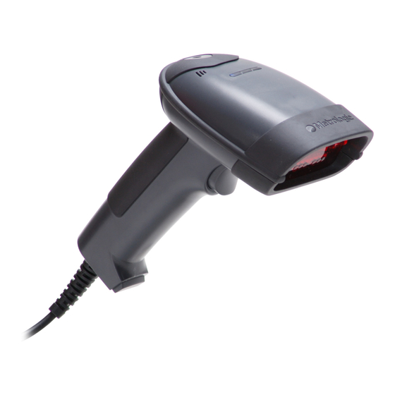
Page 8: Scanner Components
NTRODUCTION Scanner Components Figure 1. Scanner Components Item Description Yellow LED See Visual Indicators (on page 17) White LED See Visual Indicators (on page 17) Blue LED See Visual Indicators (on page 17) Speaker See Audible Indicators (on page 16) Trigger Red Window LED Aperture... -
Page 9: The Powerlink Cable
NTRODUCTION The PowerLink Cable Connecting Important: If the PowerLink cable is not fully ‘latched’ the unit can power intermittently. Figure 2. Figure 3. Disconnecting Before removing the cable from the scanner, Metrologic recommends that the power on the host system is off and the power supply has been disconnected from the PowerLink cable. -
Page 10: Labels
NTRODUCTION Labels Each scanner has a label located on the underside of the head. This label provides the unit’s model number, date of manufacture, serial number, CE and caution information. The following figure gives an example of the label and its location. -
Page 11: Installing The Scanner To The Host System
NSTALLING THE CANNER TO THE YSTEM RS232 MS1690-14 Turn off the host device. Plug the male 10-pin RJ45 end of the PowerLink cable into the 10-pin socket on the MS1690. There will be an audible click when the connector lock engages. Connect the 9-pin D-type connector of the communication cable to the proper COM port of the host device. -
Page 12: Keyboard Wedge Ms1690-47
NSTALLING THE CANNER TO THE YSTEM Keyboard Wedge MS1690-47 Turn off the host device. Plug the 10-pin RJ45 male end of the PowerLink cable into 10-pin socket on the MS1690. There will be an audible click when the connector lock engages. Disconnect the keyboard from the host device. -
Page 13: Stand Alone Keyboard Ms1690-47
NSTALLING THE CANNER TO THE YSTEM Stand Alone Keyboard MS1690-47 Turn off the host device. Plug the male 10-pin RJ45 end of the PowerLink cable into the 10-pin socket on the MS1690. There will be an audible click when the connector lock engages. -
Page 14: Ibm Ms1690-11
NSTALLING THE CANNER TO THE YSTEM IBM MS1690-11 Turn off the host device. Plug the male 10-pin RJ45 end of the MVC cable into the 10-pin socket on the MS1690. There will be an audible click when the connector lock engages Connect the other end of the MVC cable to the host device. -
Page 15: Full Speed Usb Ms1690-40 (Integrated)
NSTALLING THE CANNER TO THE YSTEM Integrated USB: Full Speed MS1690-40 Low Speed MS1690-38 Turn off the host device. Plug the male 10-pin RJ45 end of the USB cable into the 10-pin socket on the MS1690. There will be an audible click when the connector lock engages. -
Page 16: Stand Kits
TAND Stand Components, MLPN 46-00147 Figure 11. Stand Components Item Description Qty. Stand Base Qty. 1 Flexible Shaft Qty. 1 Flexible Shaft Cover Qty. 1 Scanner Cradle Qty. 1 ¼" – 20 x 3/8" Flat Head Phillips, 100° Undercut Qty. 2 #8 Round Head Wood Screw Qty. -
Page 17: Hard Mounting The Stand
TAND Hard Mounting the Stand (Optional) Metrologic provides two #8 wood screws for securing the stand base to the counter top. The following figure provides the pilot hole dimensions for securing the stand base. Figure 12. Stand Base Hole Pattern (Not to Scale) -
Page 18: Assembling The Stand
TAND Assembling the Stand Figure 13. Assembling the Stand... -
Page 19: Scanner Operation
CANNER PERATION Two Default Modes of Operation* Multi-Trigger, Out of Stand The IR detects an object in the IR activation range and automatically turns on linear illumination. Aim the scanner’s line of light over the bar code. Pull the trigger to initiate scanning. The scanner’s light output will start to flash as it attempts to scan the bar code. -
Page 20: Audible Indicators
CANNER PERATION Audible Indicators When the MS1690 is in operation, the scanner provides audible feedback. These sounds indicate the status of the scanner. Eight settings are available for the tone of the beep (normal, 6 alternate tones and no tone). To change the tone, refer to the MetroSelect Single-Line Configuration Guide, 00-02544 or MLPN... -
Page 21: Visual Indicators
CANNER PERATION Visual Indicators The MS1690 has three LED indicators (yellow, white and blue) located on the top of the scanner. When the scanner is on, the flashing or stationary activity of the LEDs indicates the status of the current scan and the scanner. No LEDs are Illuminated The LEDs will not be illuminated if the scanner is not receiving power from the host or transformer. -
Page 22: Failure Modes
CANNER PERATION Failure Modes Long Razzberry Tone – During Power Up Failed to initialize or configure the scanner. If the scanner does not respond after reprogramming, return the scanner for repair. Short Razzberry Tone – During Scanning An Invalid bar code has been scanned when in configuration mode. -
Page 23: Depth Of Field By Minimum Bar Code Element Width
CANNER PERATION Depth of Field by Minimum Bar Code Element Width INIMUM LEMENT IDTH .132 .254 .533 .254 .381 mils 10.4 15.9 Figure 16. Depth of Field by Minimum Bar Code Element Width Specifications are subject to change without notice. -
Page 24: Ir Activation Range
CANNER PERATION IR Activation Range The MS1690 has a built in object detection sensor that instantly turns on the scanner when an object is presented within the scanner’s IR activation Area. Figure 17. IR Activation Area Specifications are subject to change without notice... -
Page 25: Troubleshooting Guide
ROUBLESHOOTING UIDE The following guide is for reference purposes only. Contact a Metrologic representative at 1-800-ID-Metro or 1-800-436-3876 to preserve the limited warranty terms. All Interfaces MS1690 Series Troubleshooting Guide Symptoms Possible Causes Solution No power is being Check transformer, outlet and supplied to the power strip. - Page 26 ROUBLESHOOTING UIDE Symptoms Possible Causes Solution The unit powers The beeper is up, but does not Enable the beeper and select a disabled and no tone beep when bar tone. is selected. code is scanned. UPC/EAN, Code 39, interleaved 2 The unit powers The bar code of 5, Code 93, Code 128, Codabar...
- Page 27 ROUBLESHOOTING UIDE Symptoms Possible Causes Solution Check print mode. The type of The print quality of printer could be the problem. the bar code is Change print settings (i.e. change suspect. to econo mode or high speed). Check print mode. The type of The aspect ratio of printer could be the problem.
- Page 28 ROUBLESHOOTING UIDE Symptoms Possible Causes Solution Increase interscan code delay The unit is setting. Adjust whether the F0 transmitting The configuration is break is transmitted. It may be each character not set correctly. necessary to try this in both twice. settings.
-
Page 29: Design Specifications
ESIGN PECIFICATIONS MS1690 D ESIGN PECIFICATIONS PERATIONAL Light Source: LED 645 nm Pulse Duration: 1 ms to 8 ms Maximum Output Maximum 85 mA emits 3,120 mlm of an Osram LED: 0 mm – 254 mm (0" – 10") for Depth of Scan Field: 0.330 mm (13 mil) Bar Code at Default Setting 49 mm W x 19 mm H (1.9”... - Page 30 ESIGN PECIFICATIONS MS1690 D ESIGN PECIFICATIONS LECTRICAL Input Voltage: 5.0VDC ± 0.25V Peak = 2 W (Typical) Operating = 1.65 W (Typical) Power: Idle / Standby = 800 mW (Typical) Peak = 400 mA (Typical) Current: Operation = 330 mA (Typical) Idle / Standby = 160 mA (Typical) DC Transformer: Class 2;...
-
Page 31: Applications And Protocols
PPLICATIONS AND ROTOCOLS The model number on each scanner includes the scanner number and factory default communications protocol. ERSION CANNER OMMUNICATION ROTOCOL DENTIFIER IBM 468X/469X, RS232-TXD, RXD, RTS, CTS RS232 (TX, RX, RTS, CTS, DTR) Low Speed USB MS1690 - Full-speed USB Keyboard Wedge, Stand-Alone Keyboard and RS232 Transmit/Receive... -
Page 32: Default Settings - Communication Parameters
– C EFAULT ETTINGS OMMUNICATION ARAMETERS Many functions of the scanner can be “configured” – that is, enabled or disabled. The scanner is shipped from the factory configured to a set of default conditions. The default parameter of the scanner has an asterisk (*) in the charts on the following pages. - Page 33 – C EFAULT ETTINGS OMMUNICATION ARAMETERS PARAMETER DEFAULT RS232 IBM 46XX Maxicode Aztec Postals Mod 43 Check on Code 39 MSI-Plessy 10/10 Check Digit MSI-Plessy Mod 10 Check Digit Paraf Support ITF ITF Symbol Lengths Variable Symbol Length Lock None Beeper tone Normal Before...
- Page 34 – C EFAULT ETTINGS OMMUNICATION ARAMETERS PARAMETER DEFAULT RS232 IBM 46XX Transmit lead zero on UPC-E Transmit UPC-A number system Transmit UPC-A Manufacturer ID# Transmit UPC-A Item ID# Transmit Codabar Start/Stop Characters CLSI Editing (Enable) Transmit Mod 43 Check digit on Code 39 Transmit Mod 10/ITF Transmit MSI-Plessy...
- Page 35 – C EFAULT ETTINGS OMMUNICATION ARAMETERS PARAMETER DEFAULT RS232 IBM 46XX XON/XOFF Handshaking ACK/NAK Two Digit Supplements Five Digit Supplements Bookland 977 (2 digit) Supplemental Requirement Supplements are not Required Two Digit Redundancy Five digit Redundancy Coupon Code 128 † Configurable Code Lengths 7 avail †...
-
Page 36: Configuration Modes
ONFIGURATION ODES The MS1690 Series has three modes of configuration. • Bar Codes The MS1690 can be configured by scanning the bar codes included in the Metrologic Single-Line Configuration Guide ( 00-02544). This manual MLPN can be downloaded for FREE from Metrologic’s website (www.metrologic.com). -
Page 37: Upgrading The Flash Rom Firmware
ROM F PGRADING THE LASH IRMWARE The MS1690 Focus is part of Metrologic's line of scanners with flash upgradeable firmware. The upgrade process requires a new firmware file supplied to the customer by a customer service representative and Metrologic's MetroSet2 software . -
Page 38: Scanner And Cable Terminations
CANNER AND ABLE ERMINATIONS Scanner Pinout Connections MS1690-14, RS232 The MS1690 scanner Function interfaces terminate to a Ground 10-pin, RJ45 Female Socket. RS232 Transmit Output The serial # label indicates the interface enabled when the RS232 Receive Input scanner is shipped from the RTS Output factory. - Page 39 CANNER AND ABLE ERMINATIONS Scanner Pinout Connections MS1690-38, Low Speed USB Function Ground RS232 Transmit Output RS232 Receive Input RTS Output CTS Input USB D+ V USB USB D- +5VDC Shield Ground MS1690-40, Full Speed USB Function Ground RS232 Transmit Output Figure 19.
-
Page 40: Cable Connector Configurations
CANNER AND ABLE ERMINATIONS Cable Connector Configurations (Host End) “Standard” PowerLink Cable 53-53000-3 Coiled Function Shield Ground RS232 Transmit Output RS232 Receive Input DTR Input/Light Pen Source Power/Signal Ground Reserved CTS Input 9-Pin D-Type Connector RTS Output +5VDC Stand Alone Keyboard PowerLink Cable 53-53020-3 Function... - Page 41 CANNER AND ABLE ERMINATIONS Cable Connector Configurations (Host End) Keyboard Wedge PowerLink Cable 53-53002-3 Coiled Function Keyboard Clock Keyboard Data No Connect Power Ground 5-Pin DIN, Female +5 VDC Function PC Data No Connect Power Ground +5 VDC 6-Pin DIN, Male PC Clock No Connect Metrologic will supply an adapter cable with a 5-pin DIN male connector on one...
-
Page 42: Limited Warranty
IMITED ARRANTY ® The MS1690 Focus series scanners are manufactured by Metrologic at its Blackwood, New Jersey, U.S.A. facility and at its Suzhou, China facility. The MS1690 series scanners have a five (5) year limited warranty from the date of manufacture. Metrologic warrants and represents that all MS1690 series scanners are free of all defects in material, workmanship and design, and have been produced and labeled in compliance with all applicable U.S. -
Page 43: Regulatory Compliance
EGULATORY OMPLIANCE Safety ITE Equipment IEC 60950-1, EN 60950-1 Class 1 LED Product: IEC 60825-1:1993+A1+A2, EN 60825-1:1994+A1+A2 Caution Use of controls or adjustments or performance of procedures other than those specified herein may result in hazardous radiation exposure. Under no circumstances should the customer attempt to service the LED scanner. -
Page 44: Emc
EGULATORY OMPLIANCE Emissions FCC Part 15, ICES-003, CISPR 22, EN 55022 Immunity CISPR 24, EN 55024 Changes or modifications not expressly approved by the party responsible for compliance could void the user’s authority to operate the equipment. Class A Devices The following is applicable when the scanner cable is greater in length than 3 meters (9.8 feet) when fully extended: Les instructions ci-dessous s’appliquent aux cables de scanner dépassant 3 métres... - Page 45 EGULATORY OMPLIANCE Changes or modifications not expressly approved by the party responsible for compliance could void the user’s authority to operate the equipment. Class B Devices The following is applicable when the scanner cable is less than 3 meters (9.8 feet) in length when fully extended: Les instructions ci-dessous s’appliquent aux cables de scanner ne dépassant pas 3 métres (9.8 pieds) de long en extension maximale: Folgendes trifft zu, wenn das Scannerkabel kürzer als 3 Meter ist:...
-
Page 46: Patents
ATENTS This METROLOGIC product may be covered by, but not limited to, one or more of the following U.S. Patents: U.S. Patent No.: 7,086,595; 7,128,266; 7,213,762; 7,216,810; 7,225,988; 7,225,989; No license right or sublicense is granted, either expressly or by implication, estoppel, or otherwise, under any METROLOGIC or third party intellectual property rights (whether or not such third party rights are licensed to METROLOGIC), including any third party patent listed above, except for an implied license only for the normal intended use of the specific... -
Page 47: Index
NDEX AC ......... 2, 8–13, 29 EMC........ 29, 46, 48 Accessories ........2 EMI ........46, 48 Adapter........2, 42 Emissions......46, 48 Aperture.........5 Audible Indicator....19–20, 37 Firmware ........37 Flash ROM........37 Bar Code ....23–26, 27, 36 Bar Code Element .......21 Beep .... - Page 48 NDEX Mechanical ......27 Operational......27 Maintenance........7 Stand ......4, 14–16, 17 MetroSelect ..... 18, 30, 36 Stand Alone Keyboard ....2 MetroSet2........37 ® Swiftdecoder ....... 1 Mode of Operation.......17 Tone........19–20 Notices ........44 Alternate ........18 Transformer ....2, 8–13, 29 Trigger ..........
- Page 52 January 2008 Printed in USA 0 0 - 0 2 0 9 8 F...
Need help?
Do you have a question about the MK1690-61A38 and is the answer not in the manual?
Questions and answers