Table of Contents
Advertisement
TopPage
[1] SPECIFICATIONS . . . . . . . . . . . . . . . . . . . . . . . . . . . . . . . . . . . . . . 1-1
[2] EXTERNAL VIEW AND INTERNAL STRUCTURE . . . . . . . . . . . . . 2-1
[3] ADJUSTMENTS . . . . . . . . . . . . . . . . . . . . . . . . . . . . . . . . . . . . . . . 3-1
[4] MAINTENANCE . . . . . . . . . . . . . . . . . . . . . . . . . . . . . . . . . . . . . . . . 4-1
[5] DISASSEMBLY AND ASSEMBLY. . . . . . . . . . . . . . . . . . . . . . . . . . 5-1
[6] OPERATIONAL DESCRIPTIONS . . . . . . . . . . . . . . . . . . . . . . . . . . 6-1
[7] ELECTRICAL SECTION . . . . . . . . . . . . . . . . . . . . . . . . . . . . . . . . . 7-1
Parts marked with "
" are important for maintaining the safety of the set. Be sure to replace these parts with
specified ones for maintaining the safety and performance of the set.
SERVICE MANUAL
DIGITAL MULTIFUNCTIONAL
SYSTEM OPTION
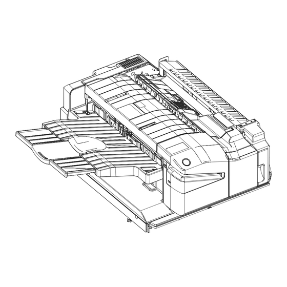
FINISHER
PUNCH UNIT
MODEL
CONTENTS
SHARP CORPORATION
CODE: 00ZMXFN27/S2E
MX-FN27
MX-PN14
This document has been published to be used
for after sales service only.
The contents are subject to change without notice.
Advertisement
Table of Contents


Need help?
Do you have a question about the MX-FN27 and is the answer not in the manual?
Questions and answers