Gaggenau VG 231 Operating And Assembly Instructions Manual
Gas cooker
Hide thumbs
Also See for VG 231:
- Instruction book (21 pages) ,
- Installation instructions (4 pages) ,
- Instruction manual (48 pages)
Table of Contents
Advertisement
Advertisement
Table of Contents

Related Manuals for Gaggenau VG 231


Summary of Contents for Gaggenau VG 231
- Page 1 Operating and assembly instructions VG 231 Gas cooker...
-
Page 2: Table Of Contents
VG 231 Preface 1. Important notes Page 3-4 1.1 For your safety Page 3 1.2 Operating for the first time Page 3 1.3 About use Page 4 2. Structure and operating principle Page 5-6 2.1 Structure Page 5 2.2 Special accessories Page 5 2.3 Operating principle... -
Page 3: Preface
Preface Cooking with your new gas hob will be even more fun than before. The appliance offers you the following advantages: – Regulation from hot to cold in seconds – High safety standard thanks to thermal protection elements for the burner –... -
Page 4: Important Notes
1. Important notes 1.1 For your safety You must not operate the appliance if it is damaged. Observe caution with oils and fats. They may overheat and burn easily. Foodstuffs that are When connecting electrical appliances in the pro- prepared in fat and oil (e.g. French fries) must only ximity of the appliance, make sure that connecting be prepared under constant supervision! leads do not come into contact with hot cooking... -
Page 5: About Use
In the event of malfunctions, contact your more costs will be saved. specialist dealer or your responsible Gaggenau after-sales service. It is not permitted to use grilling stones because the... -
Page 6: Structure And Operating Principle
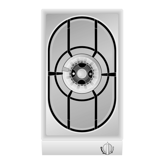
2. Structure and operating principle 2.1 Structure 1 Spark plug for automatic ignition 2 Wok burner 0.25 - 5 kW 3 Thermal fuse for flame monitor 4 Pot support 5 Control knob for the cooking position Fig. 2 6 Burner cover 7 Burner ring 8 Burner head recess 9 Burner head... -
Page 7: Operating Principle
2.3 Operating principle The total rated thermal load amounts to: The appliance features one-hand operation. That is 5.0 kW referred to H s * (gross calorific value) to say, the ignition is activated when the control 4.5 kW referred to H i (calorific value) knob is pressed briefly. -
Page 8: Operation
3. Operation The cooking positions must only be ignited when all burner parts are fitted. Otherwise, malfunctions may occur on the ignition unit. Switching on (Fig. 4): – Place a pot or a pan on the corresponding cooking position. – Press in the control knob fully and keep it pressed. -
Page 9: Cleaning And Care
4. Cleaning and care Please thoroughly clean the appliance before operating it for the first time and after every use. – Wait until the appliance has cooled down. – Remove the pot grid. – Remove the burner cover and the burner ring. –... -
Page 10: Maintenance
If the power supply is functioning correctly, but your appliance still does not work, please contact your dealer or your local Gaggenau customer service agency. Specify the appliance type (see rating plate). Repairs may only be carried out by authorised electricians, in order to guarantee the safety of the appliance. -
Page 11: Technical Data / Table
6. Technical data / Table Technical data (gas) Technical data (electrical) Burners: super strong burner Rated consumption 0.8 W Stage 4 full flame 5.0 kW Voltage 220 - 240 V Stage 3 small outer flame plus stage 2 full inner flame 1.0 kW 50 - 60 Hz Frequency... -
Page 12: Practical Tips
7. Practical tips 7.1 The wok and accessories 7.2 Cooking in the wok (not included in the scope of delivery) You can fry, steam, deep fry, stew and cook normally. – The “original wok" is the ideal wok for your gas Stir frying is the special cooking method for the cooker. -
Page 13: Recipes
7.3 Recipes Beef in oyster sauce Chicken in basil and tomato sauce Ingredients for 4 persons Ingredients for 4 persons 500 g fillet of beef 100 g of shallots 1/2 teaspoon of black pepper (freshly ground) 500 g of fillet of chicken breast 2 tablespoons of dark soya sauce 750 g of tomatoes 1 tablespoon of wheat flour... -
Page 14: Assembly Instructions
Wall trims must be heat-resistant, and the minimum VG 231-... FDxxxx distance between the hob and the wall trim is at AC 220-240V... -
Page 15: Gas Connection / Electrical Connection
8.2 Connecting the appliance 8.2.1 Gas connection Gas connection The gas connection must be in a location that permits access to the shut-off valve and which, if applicable, is visible after opening the door of the furniture item. By means of the included R 1/2” connection bracket (on the appliance end) with the affiliated washer, the appliance must be connected to a fixed connecting line or a gas safety hose to DIN 3383... -
Page 16: Nozzle Replacement
8.3 Nozzle replacement Changing over to a different gas type Only authorised specialists are permitted to change over to a different gas type. The nozzles needed for the gas type to be set are available as a conversion kit. Please specify the appliance type and the required gas type. - Page 17 Replacing the low setting nozzles (Fig. 11) The low setting nozzles for the inner (2) and outer (1) burners are located in the gas valve. They must be replaced according to the new gas type and as specified in the low setting nozzle table. Screw in the nozzles fully and check that they are tight (metallic seal).
- Page 18 First air regulation First air regulation may be necessary to always achieve a stable and low-noise flame in the event of deviating gas types and pressures. First air regulation for outer burner (Fig. 14) After undoing the screw (2) (7 mm), move the air distance in mm regulation sleeve (1) in the direction of the nozzle (3)or away from the nozzle up to a maximum...
-
Page 19: Installing The Appliance
8.4 Installing the appliance – Produce the recess for one or several Vario appliance(s) in your worktop. Proceed as indicated on the installation sketch and the dimension table. The dimension table contains details of the space requirement for the trim between the appliances.
Need help?
Do you have a question about the VG 231 and is the answer not in the manual?
Questions and answers