Sign In
Upload
Download
Table of Contents
Contents
Add to my manuals
Delete from my manuals
Share
URL of this page:
HTML Link:
Bookmark this page
Add
Manual will be automatically added to "My Manuals"
Print this page
×
Bookmark added
×
Added to my manuals
Manuals
Brands
SystemAir Manuals
Fan
EX 140A-2
Installation,operation and maintenance instruction
SystemAir EX 140A-2 Installation,Operation And Maintenance Instruction
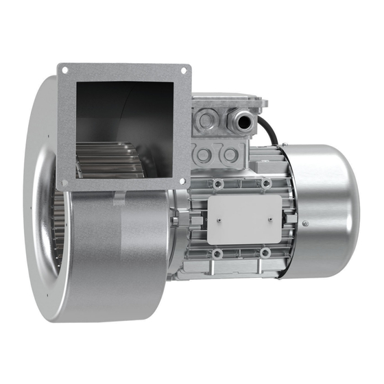
Centrifugal explosion proof fan
Hide thumbs
Also See for EX 140A-2
:
Installation, operation and maintenance instructions
(24 pages)
1
Table Of Contents
2
3
4
5
6
7
8
9
10
11
12
13
14
15
16
17
18
19
20
21
22
page
of
22
Go
/
22
Contents
Table of Contents
Troubleshooting
Bookmarks
Table of Contents
Table of Contents
1 Introduction
Product Description
Intended Use
Document Description
Product Overview
Name Plate
Classification and Certification
Type Designation
Product Liability
2 Safety
Safety Definitions
Safety Instructions
Personal Protective Equipment
3 Transportation and Storage
4 Installation
To Do before the Installation of the Product
To Install the Product
To Connect the Ducts to the Product
5 Electrical Connection
To Do before the Electrical Connection
To Connect the Product to the Power Supply
6 Commissioning
To Do before the Commissioning
To Do the Commissioning
7 Operation
To Start the Product
To Stop the Product
To Stop the Product in an Emergency
8 Maintenance
Maintenance Schedule
To Clean the Product
Spare Parts
9 Troubleshooting
10 Disposal
To Disassemble and Discard the Parts of the Product
11 Warranty
12 Technical Data
13 Product Dimensions
14 Wiring Diagrams
Wiring Diagram for Motor Protection for ATEX Motors
Wiring Diagram for Speed Controller for ATEX Motors
15 Accessory Overview
Advertisement
Quick Links
Download this manual
Installation, Operation and Maintenance instruction
EN
EX Centrifugal Explosion proof fan
Table of
Contents
Previous
Page
Next
Page
1
2
3
4
5
Advertisement
Table of Contents
Need help?
Do you have a question about the EX 140A-2 and is the answer not in the manual?
Ask a question
Questions and answers
Related Manuals for SystemAir EX 140A-2
Fan SystemAir EX 140-4C NC Installation, Operation And Maintenance Instructions
Centrifugal explosion proof fan (24 pages)
Fan SystemAir PRF 125 Series Installation And Operating Instrucitons
Plastic fans - industrial fans for aggressive gases/vapours (26 pages)
Fan SystemAir PRF Series Installation, Operation And Maintenance Instructions
Plastic fans — industrial fans for “aggressive gases/ vapours” (30 pages)
Fan SystemAir Ex 140-2 Operation And Maintenance Instructions
Explosion-proof fans (69 pages)
Fan SystemAir EX 140-4 Operation And Maintenance Instructions
Fans for explosion hazardous areas (55 pages)
Fan SystemAir EX 140-2 Operating And Maintenance Instructions Manual
Fans for explosion hazardous areas (18 pages)
Fan SystemAir EX 140A Operation And Maintenance Instructions
Explosion proof fans (20 pages)
Fan SystemAir EX 180A Operation And Maintenance Instructions
Explosion proof fans (20 pages)
Fan SystemAir EX Series Installation And Operating Instructions Manual
(107 pages)
Fan SystemAir EX 140A-4C Installation,Operation And Maintenance Instruction
Centrifugal explosion proof fan (22 pages)
Fan SystemAir EX 180A-4C Installation,Operation And Maintenance Instruction
Centrifugal explosion proof fan (22 pages)
Fan SystemAir EX 180-4C NC Installation, Operation And Maintenance Instructions
Centrifugal explosion proof fan (24 pages)
Fan SystemAir ESSVENT Operation And Maintenance Instructions
(14 pages)
Fan SystemAir EC Series Operating And Maintenance
(108 pages)
Fan SystemAir EE VTR 250/B User Manual
(18 pages)
Fan SystemAir EE VSR 150/B Service & Accessories Installation Manual
Heat recovery ventilation unit (38 pages)
This manual is also suitable for:
Ex140a-2c
Ex 140a-4
Ex 140a-4c
Ex 180a-4
Ex 180a-4c
Table of Contents
Print
Rename the bookmark
Delete bookmark?
Delete from my manuals?
Login
Sign In
OR
Sign in with Facebook
Sign in with Google
Upload manual
Upload from disk
Upload from URL


Need help?
Do you have a question about the EX 140A-2 and is the answer not in the manual?
Questions and answers