Table of Contents
Advertisement
Quick Links
224ANS
PREFERREDt SERIES HEAT PUMP
WITH PURONr REFRIGERANT
1−1/2 TO 5 NOMINAL TONS
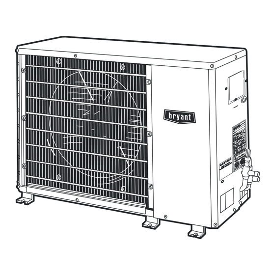
Fig. 1 - 224ANS
NOTE: Read the entire instruction manual before starting the
installation.
TABLE OF CONTENTS
. . . . . . . . . . . . . . . . . . . . . . . . . . . . . . . . .
. . . . . . . . . . . . . . . . . . . . . . . . . . . . . .
. . . . . . . . . . . . . . . . . . . . . . . . . . . . . . . . . . . . . . . .
. . . . . . . . . . . . . . . . . . . . . . . . . . . . . . . . . . . . . . . . .
MAINTENANCE
. . . . . . . . . . . . . . . . . . . . . . . . . . . . . . . . .
Installation Instructions
PAGE
. . . . . . . . . . . . . . . . . . . . . . . .
2−4
. . . . . . . . . . . . . . . . . . .
. . . . . . . . . . . . .
. . . . . . . . . . . . . . . . . . . . . . . .
7−9
SAFETY CONSIDERATIONS
Improper installation, adjustment, alteration, service, maintenance,
or use can cause explosion, fire, electrical shock, or other
conditions which may cause death, personal injury, or property
damage. Consult a qualified installer, service agency, or your
distributor or branch for information or assistance. The qualified
installer or agency must use factory−authorized kits or accessories
when modifying this product. Refer to the individual instructions
packaged with the kits or accessories when installing.
Follow all safety codes. Wear safety glasses, protective clothing,
and work gloves. Use quenching cloth for brazing operations.
Have a fire extinguisher available. Read these instructions
thoroughly and follow all warnings or cautions included in
literature and attached to the unit. Consult local building codes and
the current editions of the National Electrical Code (NEC)
NFPA70.
In Canada, refer to the current editions of the Canadian Electrical
Code CSA C22.1.
Recognize safety information. This is the safety−alert symbol
When you see this symbol on the unit and in instructions or
manuals, be alert to the potential for personal injury. Understand
the signal words DANGER, WARNING, and CAUTION. These
words are used with the safety−alert symbol. DANGER identifies
the most serious hazards which will result in severe personal injury
1
or death. WARNING signifies hazards which could result in
personal injury or death. CAUTION is used to identify unsafe
practices which may result in minor personal injury or product and
2
property damage. NOTE is used to highlight suggestions which
2
will result in enhanced installation, reliability, or operation.
3
!
4
4
ELECTRICAL SHOCK HAZARD
5
!
ENVIRONMENTAL HAZARD
Failure to follow this caution may result in environmental
pollution.
Remove and recycle all components or materials (i.e. oil,
refrigerant, etc.) before unit final disposal.
WARNING
.
Advertisement
Table of Contents

Subscribe to Our Youtube Channel
Related Manuals for Bryant PREFERRED 224ANS


Summary of Contents for Bryant PREFERRED 224ANS
-
Page 1: Table Of Contents
224ANS PREFERREDt SERIES HEAT PUMP WITH PURONr REFRIGERANT 1−1/2 TO 5 NOMINAL TONS Installation Instructions SAFETY CONSIDERATIONS Improper installation, adjustment, alteration, service, maintenance, or use can cause explosion, fire, electrical shock, or other conditions which may cause death, personal injury, or property damage. -
Page 2: Installation
INSTALLATION Check AccuRater Metering Device − Heating Mode The correct AccuRater (bypass type) refrigerant control is required IMPORTANT: Effective January 1, 2015, all split system and for system capacity optimization. An AccuRater device with packaged air conditioners must be installed pursuant to applicable field−replaceable piston is supplied with the outdoor unit (see Fig. -
Page 3: Complete Refrigerant Piping Connections
Operating Ambient Long Line Application Guide for required accessories. If either refrigerant tubing or indoor coil is exposed to the atmosphere, the Minimum outdoor operating ambient in cooling mode is 55_F system must be evacuated following good refrigeration practices. (13_C), maximum 125_F (52_C). Run refrigerant tubes as directly as possible, avoiding unnecessary Rigging turns and bends. -
Page 4: Make Electrical Connections
CAUTION UNIT DAMAGE HAZARD Failure to follow this caution may result in equipment damage or improper operation. To prevent damage to unit or service valves observe the following: LEGEND — National Electrical Code S Use a brazing shield. — Terminal Board —... -
Page 5: Service
SERVICE WARNING WARNING PERSONAL INJURY HAZARD ELECTRICAL SHOCK HAZARD Failure to follow this warning could result in personal injury or death. Failure to follow this warning could result in personal injury or death. attempt simulate these system abnormalities − high pressures pose a serious safety Before installing, modifying, or servicing system, main hazard. - Page 6 Refrigerant Charging The defrost timer limits defrosting period to 10 minutes. Normally, the frost is removed and the defrost thermostat contacts open to WARNING terminate defrosting before 10 minutes have elapsed. When defrosting is terminated, the outdoor−fan motor is energized, and reversing valve solenoid is de−energized, returning unit to heating PERSONAL INJURY...
- Page 7 Heating Check Chart Procedure − Heating Mode 4. Measure outdoor dry−bulb temperature with thermometer. To check system operation during heating cycle, refer to the 5. Measure indoor air (entering indoor coil) wet−bulb Heating Check Chart on outdoor unit. This chart indicates whether temperature with a sling psychrometer.
- Page 8 Table 1—Horizontal Discharge Outdoor Units − Adjusted Subcooling Subcooling Delta from Rating Plate Value Indoor Unit Outdoor Unit Tonnage CAP**1814A** –– CNPV*1814A** –– FB4CNP018L –– FFMANP019 –– FPMBN*018 –– FX4DNF019L –– CAP**24**A** –– –– CNP**24**A** –– –– CSPH*2412A** –– FB4CNP024L ––...
- Page 9 Table 2—Superheat Charging OUT- EVAPORATOR ENTERING AIR TEMPERATURE °F (°C) WB DOOR TEMP °F (10) (11) (12) (13) (14) (16) (17) (18) (19) (20) (21) (22) (23) (24) (°C) (13) (-13) (-11) (-10) (-8) (-7) (-5) (-3) (-2) (16) (-14) (-12) (-11) (-9)
- Page 10 Bryant Heating & Cooling Systems. S 7310 W. Morris St. S Indianapolis, IN 46231 Edition Date: 02/15 Catalog No: II224ANS-02 Manufacturer reserves the right to change, at any time, specifications and designs without notice and without obligations. Replaces: II224ANS-01...
Need help?
Do you have a question about the PREFERRED 224ANS and is the answer not in the manual?
Questions and answers