Table of Contents
Advertisement
Quick Links
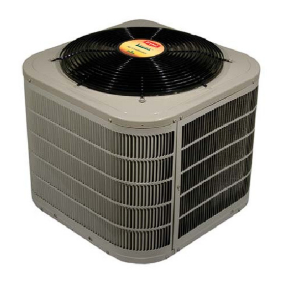
MODEL 223A / 224A
LEGACYT SERIES HEAT PUMP
WITH PURONR REFRIGERANT
SIZES 018 TO 060
1- -1/2 TO 5 NOMINAL TONS
Fig. 1 --- 223A / 224A
NOTE: Read the entire instruction manual before starting the
installation.
Installation Instructions
TM
a05236
TABLE OF CONTENTS
. . . . . . . . . . . . . . . . . . . . . . . . . . . . . .
Step 2 - - Install on Solid Pad
. . . . . . . . . . . . . . . . . . . . . . . . . . .
. . . . . . . . . . . . . . . . . . . . . . . . .
. . . . . . . . . . . . . . . . . . . . . . . . . .
. . . . . . . . . . . . . . . . . . . . . . . . . .
PAGE
. . . . . . . . . . . . . . . . . . . . . . .
. . . . . . . . . . . . .
3 - - 12
. . . . . . . . . . . . . . .
. . . . . . . . . . . . . . . . . . . . . .
. . . . . . . . . . . . . . . . . .
. . . . . . . . . . . . . . . . . . . . . .
3 - - 4
. . . . . . . . . . . . . . . . .
. . . . . . . . . . . . . .
5 - - 7
. . . . . . . . . . . .
7 - - 8
. . . . . . . . . . . . .
. . . . . . . . . . . . . .
9 - - 11
. . . . . . . . . . . . . . . . . . . . . . . . .
. . . . . . . . . . . . . . . . . . . . . .
2
2
3
3
3
3
3
5
8
8
12
12
12
Advertisement
Table of Contents

Subscribe to Our Youtube Channel
Related Manuals for Bryant LEGACY 223A


Summary of Contents for Bryant LEGACY 223A
-
Page 1: Table Of Contents
MODEL 223A / 224A LEGACYT SERIES HEAT PUMP WITH PURONR REFRIGERANT SIZES 018 TO 060 1- -1/2 TO 5 NOMINAL TONS Installation Instructions TABLE OF CONTENTS PAGE SAFETY CONSIDERATIONS ..... . . INSTALLATION RECOMMENDATIONS . -
Page 2: Safety Considerations
SAFETY CONSIDERATIONS INSTALLATION RECOMMENDATIONS Improper installation, adjustment, alteration, service, NOTE: In some cases noise in the living area has been traced to maintenance, or use can cause explosion, fire, electrical shock, or gas pulsations from improper installation of equipment. other conditions which may cause death, personal injury, or 1. -
Page 3: Installation
STEP 4 —Operating Ambient INSTALLATION STEP 1 —Check Equipment and Job Site The minimum outdoor operating ambient in cooling mode is 55°F, and the maximum outdoor operating ambient in cooling Unpack Unit mode is 125°F. The maximum outdoor operating ambient in Move to final location. - Page 4 Installing TXV in Place of Piston Replacing TXV on R- -22 Indoor Coil 1. Pump system down to 2 psig and recover refrigerant. 1. Pump system down to 2 psig and recover refrigerant. 2. Remove hex nut from piston body. Use backup wrench on 2.
-
Page 5: Step 7 -Check Defrost Thermostat
STEP 7 —Check Defrost Thermostat CAUTION Check defrost thermostat to ensure it is properly located and securely attached. There is a liquid header with a brass distributor UNIT DAMAGE HAZARD and feeder tube going into outdoor coil. At the end of the one of the feeder tubes, there is a 3/8 in. - Page 6 Table 2—Refrigerant Connections and Recommended Liquid and Vapor Tube Diameters (In.) VAPOR (up to 80 ft.) LIQUID UNIT SIZE Connection Diameter Tube Diameter Connection Diameter Rated Tube Diameter 018, 024 030, 036 042, 048 1- - 1/8 Notes: 1. Tube diameters are for total equivalent lengths up to 80 ft.. 2.
-
Page 7: Step 9 -Make Electrical Connections
Deep Vacuum Method Final Tubing Check The deep vacuum method requires a vacuum pump capable of IMPORTANT: Check to be certain factory tubing on both pulling a vacuum of 500 microns and a vacuum gage capable of indoor and outdoor unit has not shifted during shipment. Ensure accurately measuring this vacuum depth. -
Page 8: Step 10 -Compressor Crankcase Heater
Connect Ground and Power Wires Connect Control Wiring Connect ground wire to ground connection in control box for Route 24v control wires through control wiring grommet and safety. Connect power wiring to contactor as shown in Fig. 10. connect leads to control wiring. See Thermostat Installation Instructions for wiring specific unit combinations. -
Page 9: Step 12 -Start- -Up
STEP 12 —Start- -Up Follow these steps to properly start up system: 1. After system is evacuated, fully open liquid and vapor CAUTION service valves. 2. Unit is shipped with valve stem(s) closed and caps UNIT OPERATION AND SAFETY HAZARD installed. - Page 10 HEAT TYPICAL HP THERMOSTAT PUMP FAN COIL 24 VAC HOT 24 VAC COM HEAT STAGE 2 COOL/HEAT STAGE 1 INDOOR FAN RVS COOLING EMERGENCY IF AVAILABLE HEAT LEGEND 24-V FACTORY WIRING 24-V FIELD WIRING FIELD SPLICE CONNECTION OUTDOOR THERMOSTAT EMERGENCY HEAT RELAY SUPPLEMENTAL HEAT RELAY A02325 / A97413 Fig.
- Page 11 Sequence of Operation QUIET SHIFT Quiet shift is a field selectable defrost mode (factory set to OFF), NOTE: Defrost control board is equipped with 5 minute lockout which will eliminate occasional noise that could be heard at the timer that is initiated upon any interruption of power. start of defrost cycle and restarting of heating cycle.
-
Page 12: Step 13 -Check Charge
STEP 13 —Check Charge Heating Check Chart Procedure Factory charge and charging method are shown on unit rating To check system operation during heating cycle, refer to the plate. To check charge in cooling mode, refer to Cooling Only Heating Check Chart on outdoor unit. This chart indicates Procedure. - Page 13 Table 4—Required Liquid- -Line Temperature Liquid Liquid Pressure Pressure Required Subcooling Temperature Required Subcooling Temperature °F) °F) at Service at Service Valve Valve (PSIG) (PSIG)
-
Page 14: Puron Refrigerant Quick Reference Guide
PURONR (R- -410A) REFRIGERANT QUICK REFERENCE GUIDE S Puron refrigerant operates at 50---70 percent higher pressures than R ---22. Be sure that servicing equipment and replacement components are designed to operate with Puron refrigerant S Puron refrigerant cylinders are rose colored. S Recovery cylinder service pressure rating must be 400 psig, DOT 4BA400 or DOT BW400.
Need help?
Do you have a question about the LEGACY 223A and is the answer not in the manual?
Questions and answers