Advertisement
ASSEMBLY GUIDE
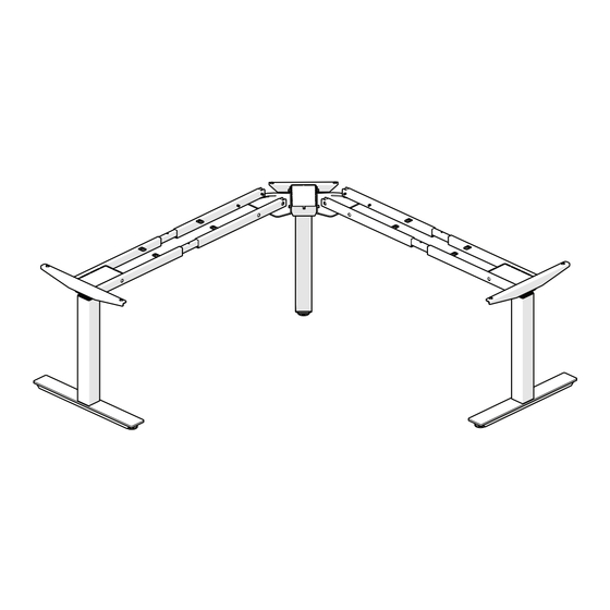
L-Shaped Electric Height Adjustable Table
Models 695777 and 695778
Read this manual thoroughly prior to installation, operation or
maintenance. Keep these instructions in a safe location for
future reference. For questions, visit globalindustrial.com or
contact Customer Service at 1-800-645-2982.
Advertisement
Table of Contents

Subscribe to Our Youtube Channel
Related Manuals for Global Industrial Interion 695777


Summary of Contents for Global Industrial Interion 695777
- Page 1 ASSEMBLY GUIDE L-Shaped Electric Height Adjustable Table Models 695777 and 695778 Read this manual thoroughly prior to installation, operation or maintenance. Keep these instructions in a safe location for future reference. For questions, visit globalindustrial.com or contact Customer Service at 1-800-645-2982.
- Page 2 ASSEMBLY GUIDE Table of contents 1. General • 1.1 About this manual • 1.2 Intended use 2. Safety Information • 2.1 Informal safety measures • 2.2 Use of the adjustable frame • 2.3 Specific Dangers • 2.4 In an emergency •...
-
Page 3: Safety Information
ASSEMBLY GUIDE 1. General 1.1 About this user manual The guiding principle for safe use and trouble-free operation of this adjustable frame is the knowledge of basic safety information and regulations. This user manual includes the most important information needed for assembling and operating the adjustable frame safely. -
Page 4: Part Check List
ASSEMBLY GUIDE 3. Packaging 31 Part Check List Leg (3 Pcs) Frame (4 Pcs) End Pipe (2 Pcs) 3rd Leg End Pipe(1 Pcs) Feet (2 Pcs) 3rd Leg Bracket(1 Set) Adjustment Feet(1 Pcs) Control Unit (1 Pcs) Remote Control (1 Pcs) Table connection (2pcs) Connection Cable (3 Pcs) Power Cable (1 Pcs) -
Page 5: Screw List
ASSEMBLY GUIDE 3. Packaging 3.2 Screw List M6x12 (18 Pcs) M8X12 (4 Pcs) ST 4.8x19 (24 Pcs) Feet Matching Screw (8 Pcs) M6x12 Steel M6x16 Aluminum M6x25 Plastic M6x30... -
Page 6: Remote Control
ASSEMBLY GUIDE 3. Packaging 3.2 Screw List Remote Control Matching Screw (2 Pcs) ST 4.2x19 M3.5X12 Before attempting assembly of the Height Adjustable Frame, please read safety information in Section 2. Torque Guide • M6 Screw’s max torque = 6nm •... - Page 7 ASSEMBLY GUIDE 4. Assembly 4.1 Assembly Step by Step M6x12 Step 1 Step 2 Assemble the middle Leg and Bracket as illustrated above. Please Mount the Adjustment Feet to the middle Leg as illustrated above. refer to Torque Guide. Please punch in, do not use a hammer. ST 4.8x19 M6x12 Step 3...
- Page 8 ASSEMBLY GUIDE 4. Assembly 4.1 Assembly Step by Step M6X16 M6x12 Step 7 Step 8 Assemble the middle Leg and 3rd Leg End Pipe as illustrated above. Mount the Feet as illustrated above. The smooth side of the plate Please refer to Torque Guide. faces the foot.
-
Page 9: Zero Setting
ASSEMBLY GUIDE 4. Assembly 4.1 Assembly Step by Step ST 2.9X16 Step 14 Step 13 Perform Zero Setting. Mount the Remote Control to the Table top as illustrated above. Please refer to Screw Part List Select the appropriate feet and the matching screw. - Page 10 ASSEMBLY GUIDE 5. Operating Instructions 5.2 General Operation: This function enables you to adjust the frame upwards or downwards. Press button and keep pressing the button until the required frame height is reached. The frame will continue moving upwards or downwards until you release the button or the maximum / minimum height is reached.
- Page 11 ASSEMBLY GUIDE 6. Programmable Remote Control Operating Instructions The following actions should only be performed by properly trained personnel. 6.1 Enter the setting menu Follow the instructions below to enter the setting menu to change the settings for the control unit. •...
- Page 12 ASSEMBLY GUIDE 6. Programmable Remote Control Operating Instructions 6.6 Changing the desktop height displayed Follow the instructions below to change the height shown on the display but not the actual position of the desktop. • Within the setting menu choose “S – 5”. •...
-
Page 13: Troubleshooting
ASSEMBLY GUIDE 7. Troubleshooting In this section you will find detailed information on the following topics: • Possible faults and remedies • Error messages on the remote control display 7.1 Possible faults and remedies Legs not working Possible Cause Remedy Ξ... - Page 14 ASSEMBLY GUIDE 7. Troubleshooting The display reads E + an error code Possible Cause Remedy Ξ There is an internal fault in the Ξ Proceed as indicated in the following list control unit Error code Note How to handle it Ξ...
- Page 15 ASSEMBLY GUIDE 7. Troubleshooting Error code Note How to handle it Ξ Motor 1 wrong direction of operation Switch the motor line or hall line Ξ Motor 1 overload Reduce load Ξ Motor 2 not connect Check the cable Ξ Motor 2 error in current sampling channel Replace the control panel Ξ...
Need help?
Do you have a question about the Interion 695777 and is the answer not in the manual?
Questions and answers