
Related Manuals for CMC S19E


Summary of Contents for CMC S19E
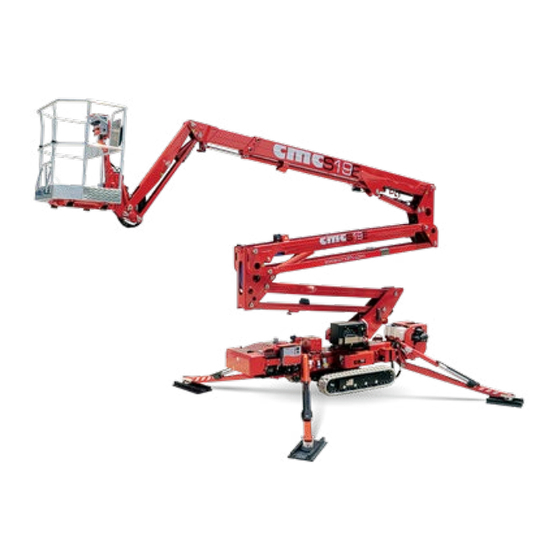
- Page 1 USE AND MAINTENANCE MANUAL Man.220 Rev.6 S19E Mobile Elevating Work Platform(MEWP)
-
Page 3: Content Of The Manual
This manual has been drawn up in order to: ❑ Provide with the instructions for the transport, handling and storage of the machine; ❑ Show the MEWP functions, features, operat- ing characteristics, limitations; MAN.220 Rev.6 ENG - Use and maintenance manual S19E page... - Page 4 * (OPTIONAL) = indicates an optional outfit. previously on similar machines or that they will MAN.220 Rev.6 ENG - Use and maintenance manual S19E page...
- Page 5 ➔ In case of loss or deterioration, the re- placement documentation must be re- MAN.220 Rev.6 ENG - Use and maintenance manual S19E page...
- Page 6 In addition, the technical safety requirements of the following international standards have been applied: Directive EN 280:2015 EN 13001-3-1 2006/42/CE Directive Directive EN ISO 2014/35/UE 2000/14/CE 12100 ISO 13849-1- ISO 3864 EN 60068-2- MAN.220 Rev.6 ENG - Use and maintenance manual S19E page...
- Page 7 No part of this publication can be translated, modi- fied or reproduced (even partially) without the ex- pressed authorization of C.M.C. s.r.l. Year 2021 C.M.C. s.r.l. MAN.220 Rev.6 ENG - Use and maintenance manual S19E page...
-
Page 8: Description And Purpose
It must be transported only when it is totally folded in the transport position. The machine is called S19E and it is a mobile ➔The use of the machine is allowed only to pro- elevating work platform (MEWP): •... -
Page 9: Tüv Certification
(EN 280 par. 1.4 - ANSI/SAIA A92.20 par. 3). Loading cycle: cycle starts from the access position, con- tinues performing the work and finishes returning to the access position. MAN.220 Rev.6 ENG - Use and maintenance manual S19E page... -
Page 10: Identification Plate
1.7 Identification plate On the MEWP turret, there is a plate with all the identification data of the machine: Picture 1: identification plate. MAN.220 Rev.6 ENG - Use and maintenance manual S19E page... -
Page 11: Specifications
(*optional) longitudinally/transversally Longitudinal 0,5 - 1,3 0.31 - 0.81 3,90 m 12.80 ft Travel speed stabilization km/h Cross stabilization 3,25 m 10.66 ft Outriggers plate Ø 0,18 m 0.59 ft MAN.220 Rev.6 ENG - Use and maintenance manual S19E page... - Page 12 0,7 m/s (2.3 ft/s) (U) Max. pressure in 205 Kg/m² 41.99 lb/ft work (4 feet opened) (2.01 KN/m²) Max allowed manual force in the 400 N basket with 1 operator MAN.220 Rev.6 ENG - Use and maintenance manual S19E page...
- Page 13 Tightening torque Bolts of the bearing M16 cl 10.9 28 daNm MAN.220 Rev.6 ENG - Use and maintenance manual S19E page...
- Page 14 2.2 Work diagram Picture 2a: work diagram with two-men aluminum basket 1400x700x1100 mm two-men fiberglass basket 1200x700x1100 mm. MAN.220 Rev.6 ENG - Use and maintenance manual S19E page...
- Page 15 Picture 2b: work diagram with one-man aluminum basket 800x700x1100 mm one-man fiberglass basket 800x600x1100 mm. MAN.220 Rev.6 ENG - Use and maintenance manual S19E page...
- Page 16 Description of the main components Picture 3: main components of the MEWP. MAN.220 Rev.6 ENG - Use and maintenance manual S19E page...
- Page 17 The basket 13 (Picture 3) is connected to the boom connecting rod are made with high quality steel sheets. The movement of the pantograph (lifting and of the telescopic element through the jib 14 (Picture MAN.220 Rev.6 ENG - Use and maintenance manual S19E page...
-
Page 18: Control Stations
The floor is in anti-skid and self- placed on the chassis, to turn on the electric system draining aluminum. and start the endothermic engine (Honda petrol en- gine or Kubota/Yanmar diesel engine). MAN.220 Rev.6 ENG - Use and maintenance manual S19E page... - Page 19 • the green light 5 (Picture 4b) indicating Picture 4a: Honda engine system power supply: it is on when the SK switching on/off station. key is in position 1; MAN.220 Rev.6 ENG - Use and maintenance manual S19E page...
- Page 20 110/120/230 V one activat- system is on, the progress of the charging pro- ed on the machine at the same time. cess will be shown by appropriate leds on the control stations. MAN.220 Rev.6 ENG - Use and maintenance manual S19E page...
- Page 21 5a - * optional) fixed to the frame. Picture 5a: power supply selector (*optional). This allows you to have electrical outlets of both voltages (Picture 5b): on the ground to MAN.220 Rev.6 ENG - Use and maintenance manual S19E page...
- Page 22 SK key is in posi- tion 1; • the led 2 (Picture 6) for aerial part use con- Figure 5b: dual power sockets. sent: if lighted on, it allows the maneuvers of MAN.220 Rev.6 ENG - Use and maintenance manual S19E page...
- Page 23 It is not possible to use two different con- The platform (operating) control station (Picture 7a) trol station at the same time. is located inside the basket, and it is formed by: MAN.220 Rev.6 ENG - Use and maintenance manual S19E page...
- Page 24 It has priority over any other (Picture 7a): upward for its lifting and down- command: it makes possible only the manual ward for its lowering. emergency lowering of the aerial part. MAN.220 Rev.6 ENG - Use and maintenance manual S19E page...
- Page 25 12 (Pic- ture 7a): during the closing operations, if the machine stops because of crash danger, it is possible to go on the operations pushing this MAN.220 Rev.6 ENG - Use and maintenance manual S19E page...
- Page 26 - pushing the lever forward, the stabilizer within the maximum value allowed by the lowers. manufacturer, that is equal to 1°. - pushing the lever backward, the stabi- lizer withdraws. MAN.220 Rev.6 ENG - Use and maintenance manual S19E page...
- Page 27 It has priority over any other o right crawler joystick J2 (Picture 9a) MAN.220 Rev.6 ENG - Use and maintenance manual S19E page...
- Page 28 P (Picture 9b): hold this button pressed to- Picture 10: platform control (emergency) station. gether the joystick J1 to lift/lower the jib MAN.220 Rev.6 ENG - Use and maintenance manual S19E page...
- Page 29 Every movement stops at release of the procedure with the manual pump. lever. dead man anti-crash bypass button 10 (Picture 10): during the closing operations, MAN.220 Rev.6 ENG - Use and maintenance manual S19E page...
- Page 30 EB (Picture 11): this red and mushroom-shaped switch blocks the machine by removing the power supply to the control circuits. It has priority over any other command: it makes possible only MAN.220 Rev.6 ENG - Use and maintenance manual S19E page...
-
Page 31: Use Procedures
MAN.220 Rev.6 ENG - Use and maintenance manual S19E page... - Page 32 We recommend the use of an anemometer, to determine direction and speed of wind. Any addition that increases the wind load on the MEWP, such as warning signs, is prohib- ited. MAN.220 Rev.6 ENG - Use and maintenance manual S19E page...
-
Page 33: Transport, Storage And Pack- Aging
Be careful not to damage machine. WARNING! In both cases, it is advisable to remove the basket to reduce encum- brances and favor the operations. MAN.220 Rev.6 ENG - Use and maintenance manual S19E page... - Page 34 Take the cabled remote control from its storage place and verify that it is correctly Check that the travel slope does not ex- connected to its feed plug (Picture 13). ceed longitudinally 17° (31%) and trans- MAN.220 Rev.6 ENG - Use and maintenance manual S19E page...
- Page 35 Picture 14: loading/uploading through ramp raneous use of the dead man parking button and machine sling. P (Picture 9) and the left joystick J1 (Picture 9) of the wired remote control. MAN.220 Rev.6 ENG - Use and maintenance manual S19E page...
- Page 36 If you choose to use the electrical* en- gine: Picture 15: control board for electrical feed. 2. With machine ready to travel (transport configuration), identify the place which is nearest to the working area to reach. MAN.220 Rev.6 ENG - Use and maintenance manual S19E page...
- Page 37 One track can be adjusted to level the chassis The MEWP has only one stabilization area, given by the openings of the front and rear outriggers. An MAN.220 Rev.6 ENG - Use and maintenance manual S19E page...
- Page 38 11. Once the basket is coupled, insert the cot- the chassis: the maximum chassis slope ter pin P and the forelock C (Picture 16). allowed is 1°. Verify the correct assembly of the basket to the jib support. MAN.220 Rev.6 ENG - Use and maintenance manual S19E page...
- Page 39 When the MEWP exceeds its maximum permitted capacity (200 Kg/441 lb), the logic system detects the overload and stops the work operations, warning with a continuous acoustic signal. MAN.220 Rev.6 ENG - Use and maintenance manual S19E page...
- Page 40 The anti-crash system, supplied as standard device, does not allow the aerial part (pantograph, boom, MAN.220 Rev.6 ENG - Use and maintenance manual S19E page...
- Page 41 23. Finally, it is possible to restart the MEWP o return the boom, engine to bring it back to the storage posi- o center the turret, tion. MAN.220 Rev.6 ENG - Use and maintenance manual S19E page...
- Page 42 With a full charge (100%), the lithium battery pack is able to perform at least 10 work cycles. A work cycle includes the following sequence of operations: 1) stabilization; 2) complete machine development; 3) complete machine return; 4) destabilization. MAN.220 Rev.6 ENG - Use and maintenance manual S19E page...
-
Page 43: Emergency Operations
It will be care and responsibility of the o on wired remote control station (Picture 9), operators, at the end of the operations, to o on turret box (Picture 11). reset the original conditions, including MAN.220 Rev.6 ENG - Use and maintenance manual S19E page... - Page 44 To withdraw the aerial part, using the aforemen- tioned feeds, operate the MEWP through the emer- gency control station on the turret (Picture 10). MAN.220 Rev.6 ENG - Use and maintenance manual S19E page...
- Page 45 4) on position 0, reach the main dis- tributor shown in Picture 18 and remove move the tap in Picture 19 upward on the the carter; position with “platform” symbol; MAN.220 Rev.6 ENG - Use and maintenance manual S19E page...
- Page 46 Picture 20 (on back of the main pump, make sure to unscrew the bolt distributor); (Picture 21) under the proportional lever on the emergency control station, so that MAN.220 Rev.6 ENG - Use and maintenance manual S19E page...
- Page 47 4 (Picture 22) and completely unscrew the same proportional valve; While return the MEWP in rest configura- tion, the deceleration ramps of the ma- neuver speeds will be inactive: therefore, MAN.220 Rev.6 ENG - Use and maintenance manual S19E page...
- Page 48 (also retract the tracks OPERATING CONDITIONS WHICH ARE INDISPENSABLE FOR A SAFETY USE OF by the red lever 5 if they are enlargeable THE MACHINE. as *optional). MAN.220 Rev.6 ENG - Use and maintenance manual S19E page...
- Page 49 DIFFERENT RECOMMENDED BECAUSE, ABSORBING CURRENT DIRECTLY FROM BATTERIES, COULD PRODUCE THEIR UNEXPECTED DISCHARGE. Picture 23: electropump. It can be activated by: MAN.220 Rev.6 ENG - Use and maintenance manual S19E page...
-
Page 50: Safety Rules
Do not use the MEWP under drug or alcohol effect; Do not use the MEWP under stress condi- tions; MAN.220 Rev.6 ENG - Use and maintenance manual S19E page... - Page 51 ➔ Carefully and chronologically follow the instruc- tions given in this manual; Do not remove or modify safety devices; MAN.220 Rev.6 ENG - Use and maintenance manual S19E page...
- Page 52 It is forbidden to operate in situations which Pay the utmost attention during stabilization: are dangerous for the safety of people; check that no one is inside the stabilization area. Do not operate in explosion hazard areas; MAN.220 Rev.6 ENG - Use and maintenance manual S19E page...
- Page 53 Do not possible obstacles; ➔ fasten the safety belts to external structures but Follow the MEWP working diagram; only to the supplied grips placed in the basket; MAN.220 Rev.6 ENG - Use and maintenance manual S19E page...
- Page 54 No material shall fall from above: fasten the working material properly; MAN.220 Rev.6 ENG - Use and maintenance manual S19E page...
- Page 55 72/245/CE and its following with other structure parts; amendments: the additional electronic in- MAN.220 Rev.6 ENG - Use and maintenance manual S19E page...
-
Page 56: Safety Devices
Before starting any operation, it is im- portant that the operator checks the per- A - Electrical devices fect functioning of these devices. ▪ Removable key for the MEWP engine ignition. MAN.220 Rev.6 ENG - Use and maintenance manual S19E page... - Page 57 ▪ Block valve and parachute valve mounted on the lifting cylinders. ▪ Manual pump for emergency operations. ▪ Oil flow regulator for the control of the descent speed. MAN.220 Rev.6 ENG - Use and maintenance manual S19E page...
-
Page 58: Residual Risks
• Do not direct the jet directly above the decals To clean electrical parts, use only dry clean- and labels. ers. MAN.220 Rev.6 ENG - Use and maintenance manual S19E page... - Page 59 3 ft. 6 in. (107 cm) 87.5 kV < x > 121 kV 4 ft. 0 in. (122 cm) 121 kV < x > 140 kV 4 ft. 6 in. (137 cm) MAN.220 Rev.6 ENG - Use and maintenance manual S19E page...
- Page 60 ➔ Before using the MEWP, it is compulsory to check the presence and the perfect readability of these decals. In case of their absence or decay, contact the Ser- vice. Picture 25: identification plate (fac-simile). MAN.220 Rev.6 ENG - Use and maintenance manual S19E page...
- Page 61 Picture 26: machine model label. Picture 27: maximum capacity in basket. Picture 28: work diagram. MAN.220 Rev.6 ENG - Use and maintenance manual S19E page...
- Page 62 Picture 29: chassis box if Honda engine. Picture 30: chassis box if Kubota engine. MAN.220 Rev.6 ENG - Use and maintenance manual S19E page...
- Page 63 Picture 31: chassis box in Picture 32: basket control station. full lithium version. Picture 33: platform (emergency) control station. MAN.220 Rev.6 ENG - Use and maintenance manual S19E page...
- Page 64 Picture 36: left and right side of wired remote control. Picture 34: emergency box. Picture 37: error codes display. Picture 38: safety belt attachment point. Picture 35: wired remote control. MAN.220 Rev.6 ENG - Use and maintenance manual S19E page...
- Page 65 Picture 42: maximum slopes for travel. Picture 40: indication of 12 V socket. Picture 43: use and maintenance manual box. Picture 41: travel directions on tracks. Picture 44: indication of maximum frame inclination. MAN.220 Rev.6 ENG - Use and maintenance manual S19E page...
- Page 66 Picture 48: indication for fuel refill. Picture 45: outriggers control station. Picture 49: indication for grease application. Picture 50: indication for engine oil type/refill/checking. Picture 46: maximum load on stabilizers. MAN.220 Rev.6 ENG - Use and maintenance manual S19E page...
- Page 67 Picture 53: indication for engine battery disconnection. Picture 57: emergency bypass. Picture 54: indication of platform fuse. Picture 58: indication of emergency manual pump. Picture 55: indication of frame coupling. MAN.220 Rev.6 ENG - Use and maintenance manual S19E page...
- Page 68 Picture 62: general obligations and prohibitions. Picture 60: tap selector for platform/stabilizers valves. Picture 63: warning for tracks lifting during stabilization. Picture 61: anti-crash bypass button. MAN.220 Rev.6 ENG - Use and maintenance manual S19E page...
- Page 69 Picture 69: prohibition to wet the machine. Picture 66: electric danger. Picture 70: warning to obligate to the consulta- tion of use and maintenance manual. Picture 67: crushing and cutting hazard. MAN.220 Rev.6 ENG - Use and maintenance manual S19E page...
- Page 70 Picture 72: compliance with ANSI and CAN/CSA rules. Picture 73: inspection tag. Picture 71: MEWP use guidelines. MAN.220 Rev.6 ENG - Use and maintenance manual S19E page...
-
Page 71: Electrical System
MEWP have been calibrated: a correct calibration of these parts (which is possi- ble only in C.M.C. or in authorized Ser- vices) is important to assure the safety of the machine. MAN.220 Rev.6 ENG - Use and maintenance manual S19E page... -
Page 72: Hydraulic System
*optional. In case of its refill or replacement, it is im- perative to comply with the technical specifications of the product already present in the system. MAN.220 Rev.6 ENG - Use and maintenance manual S19E page... -
Page 73: Maintenance
The frequent sense of the user. washing of the equipment by high-pressure water jet machines is crucial to get rid of the harmful remains MAN.220 Rev.6 ENG - Use and maintenance manual S19E page... -
Page 74: Daily Maintenance
Ser- Top up USER the turret; fuel in the tank. vice. o extend and withdraw Check the level of the Top up USER the telescopic boom. coolant liquid. MAN.220 Rev.6 ENG - Use and maintenance manual S19E page... - Page 75 Contact the OUTRIGGERS SHALL sion and withdrawal; Service. o operate the levers for NOT MOVE. the lifting and lowering telescopic boom. BOOMS SHALL MOVE. MAN.220 Rev.6 ENG - Use and maintenance manual S19E page...
- Page 76 MEWP. boom until the max tion to lift the aerial Contact the outreach indicated in part. Service. work diagram. AERIAL PART SHALL NOT MOVE. MAN.220 Rev.6 ENG - Use and maintenance manual S19E page...
- Page 77 C.M.C. strictly forbidden Check that the elec- buttons work Reset connec- USER/ trical contacts are MEWP. Contact perfectly. tions. C.M.C. the Service. not slacken. MAN.220 Rev.6 ENG - Use and maintenance manual S19E page...
-
Page 78: Weekly Maintenance
USER/ Check the tightening of the bolts of thermic engine and Replacement. USER / C.M.C. the bearing, the geared motor and auxiliary motor* air C.M.C. the frame. filters. MAN.220 Rev.6 ENG - Use and maintenance manual S19E page... -
Page 79: Annual Maintenance
USER / chine and note the results in the C.M.C. proper manual section. Operations Complete check of the whole ma- chine and note the results in the C.M.C. proper manual section. MAN.220 Rev.6 ENG - Use and maintenance manual S19E page... -
Page 80: Safety Rules During Mainte- Nance
C.M.C. only c/or C.M.C. or in authorized workshops. ➔ Wear appropriate protective clothes (gloves, goggles, etc.). It is forbidden to perform maintenance operations when the MEWP moves: make MAN.220 Rev.6 ENG - Use and maintenance manual S19E page... - Page 81 (3000 - 3600 5.7 - 6.2 Unit of rpm) Data Value measure Maximum rated pow- Ø 88 x 64 6.3 - 6.8 Bore x Stroke (3000 - 3600 rpm) Cylinder capacity MAN.220 Rev.6 ENG - Use and maintenance manual S19E page...
- Page 82 Maximum Dis- 100 (electronically plied internal combustion engine, see the mainte- charge Current limited) nance interventions indicated by the manufacturer Rated Charge Cur- 30 A (0.3 C) on its website: rent MAN.220 Rev.6 ENG - Use and maintenance manual S19E page...
- Page 83 If Maximum Current the grease does not start to drain, slowly rotate the PWM Frequency track. International Protection IP20 Weight Dimension (L*W*H) 180x310x100 mm MAN.220 Rev.6 ENG - Use and maintenance manual S19E page...
- Page 84 Composition: mixture of mineral oils, calci- 100°C, mm2/s um-lithium complex thickener, additives and Viscosity Index ASTM D2270 Teflon®. (working range: from -20°C to Pour point °C ASTM D97 +120°C) Flash point COC, °C ASTM D92 MAN.220 Rev.6 ENG - Use and maintenance manual S19E page...
- Page 85 Electrical materials: windings, commands, environment; put them in the appropriate solenoid valves and similar. containers and give them to the authorized ▪ Oils and lubricants: hydraulic oil, reducers collection centres. lubricants, lubricating greases. MAN.220 Rev.6 ENG - Use and maintenance manual S19E page...
- Page 86 Picture 81: zatore sul terreno ground Macchina stabiliz- Machine stabilized and zata inclinata inclined MAN.220 Rev.6 ENG - Use and maintenance manual S19E page...
- Page 87 (*optional) • the led on the remote connection box makes two red flashes, The remote connection system is composed of an electronic box (Picture 82) mounted on the chassis MAN.220 Rev.6 ENG - Use and maintenance manual S19E page...
- Page 88 Install on your PC the TeamViewer soft- ware (11 version) to connect to the ma- chine system, through ID and Password supplied by the manufacturer; Call C.M.C. Service for technical assis- tance. MAN.220 Rev.6 ENG - Use and maintenance manual S19E page...
-
Page 89: Troubleshooting
2. The green light does not work. 3. One of the outriggers micro-switches is Cause: 1. The green light does not work. not working. 2. Micro-switch system does not work. 3. Stabilization is insufficient. MAN.220 Rev.6 ENG - Use and maintenance manual S19E page... - Page 90 Cause: 1. Oil leakage. 2. Cylinders gaskets wear. Remedies: 1. Disable the emergency button. 2. Replace the battery. Remedies: 1. Tighten hydraulic connections. 3. Refuel. 2. Replace gaskets. 4. Refill hydraulic oil. MAN.220 Rev.6 ENG - Use and maintenance manual S19E page...
- Page 91 If the problem persists, contact the Service. _________________________________________ Contact our Service for any technical problem which is not identified nor solved by the aforesaid procedure. MAN.220 Rev.6 ENG - Use and maintenance manual S19E page...
- Page 92 The tampering or replacement of compo- nents by non-authorized staff is strictly forbidden. ➔ It is mandatory to restore the sealings af- ter use of these items. MAN.220 Rev.6 ENG - Use and maintenance manual S19E page...
- Page 93 In no other occasion shall you carry (CP) out tests with the same loads used in the overload tests. NOTES. PN: nominal capacity. CP: test load. MAN.220 Rev.6 ENG - Use and maintenance manual S19E page...
-
Page 94: Operating Tests
Lock valves on the cylinders. operating tests. We have tested the cor- Pressure relief valve for the protection rect operation of the S19E and of its safe- of the entire hydraulic circuit. ty systems. Pressure relief valves for the protec-... -
Page 95: Control Register
Periodical inspections maintenance established with the technical, dimensional and functional features indicated in the journal (par. 13.9) use and maintenance manual. ➢ Notes (par. 13.10) Date _________ C.M.C. s.r.l. __________________________ MAN.220 Rev.6 ENG - Use and maintenance manual S19E page... - Page 96 The seller The buyer The seller The buyer MAN.220 Rev.6 ENG - Use and maintenance manual S19E page...
- Page 97 The seller The buyer The seller The buyer MAN.220 Rev.6 ENG - Use and maintenance manual S19E page...
- Page 98 Place……………… Place……………… Date……………… Date……………… Stamp and signature of the responsible Stamp and signature of the responsible for the firm in charge for the firm in charge The user The user MAN.220 Rev.6 ENG - Use and maintenance manual S19E page...
- Page 99 Place……………… Place……………… Date……………… Date……………… Stamp and signature of the responsible Stamp and signature of the responsible for the firm in charge for the firm in charge The user The user MAN.220 Rev.6 ENG - Use and maintenance manual S19E page...
- Page 100 Place……………… Place……………… Date……………… Date……………… Stamp and signature of the responsible Stamp and signature of the responsible for the firm in charge for the firm in charge The user The user MAN.220 Rev.6 ENG - Use and maintenance manual S19E page...
- Page 101 Place……………… Place……………… Date……………… Date……………… Stamp and signature of the responsible Stamp and signature of the responsible for the firm in charge for the firm in charge The user The user MAN.220 Rev.6 ENG - Use and maintenance manual S19E page...
- Page 102 Place……………… Place……………… Date……………… Date……………… Stamp and signature of the responsible Stamp and signature of the responsible for the firm in charge for the firm in charge The user The user MAN.220 Rev.6 ENG - Use and maintenance manual S19E page...
- Page 103 Place……………… Place……………… Date……………… Date……………… Stamp and signature of the responsible Stamp and signature of the responsible for the firm in charge for the firm in charge The user The user MAN.220 Rev.6 ENG - Use and maintenance manual S19E page...
-
Page 104: Replacement Of Electrical Components
Place……………… Place……………… Date……………… Date……………… Stamp and signature of the responsible Stamp and signature of the responsible for the firm in charge for the firm in charge The user The user MAN.220 Rev.6 ENG - Use and maintenance manual S19E page... - Page 105 Place……………… Place……………… Date……………… Date……………… Stamp and signature of the responsible Stamp and signature of the responsible for the firm in charge for the firm in charge The user The user MAN.220 Rev.6 ENG - Use and maintenance manual S19E page...
- Page 106 Place……………… Place……………… Date……………… Date……………… Stamp and signature of the responsible Stamp and signature of the responsible for the firm in charge for the firm in charge The user The user MAN.220 Rev.6 ENG - Use and maintenance manual S19E page...
- Page 107 Place……………… Place……………… Date……………… Date……………… Stamp and signature of the responsible Stamp and signature of the responsible for the firm in charge for the firm in charge The user The user MAN.220 Rev.6 ENG - Use and maintenance manual S19E page...
- Page 108 Place………. Date…………… Place………. Date…………… Stamp and signature of the responsible Stamp and signature of the responsible for the firm in charge for the firm in charge The user The user MAN.220 Rev.6 ENG - Use and maintenance manual S19E page...
- Page 109 Place………. Date…………… Place………. Date…………… Stamp and signature of the responsible Stamp and signature of the responsible for the firm in charge for the firm in charge The user The user MAN.220 Rev.6 ENG - Use and maintenance manual S19E page...
- Page 110 The user has the obligation to respect the maintenance control program described in this manual and to register the inspections in a proper journal. DESCRIPTION OF DATE SIGNATURE THE INTERVENTION MAN.220 Rev.6 ENG - Use and maintenance manual S19E page...
- Page 111 DESCRIPTION OF DESCRIPTION OF DATE SIGNATURE DATE SIGNATURE THE INTERVENTION THE INTERVENTION MAN.220 Rev.6 ENG - Use and maintenance manual S19E page...
- Page 112 13.10 Notes …………………………………………………… …………………………………………………… …………………………………………………… …………………………………………………… …………………………………………………… …………………………………………………… …………………………………………………… …………………………………………………… …………………………………………………… …………………………………………………… …………………………………………………… …………………………………………………… …………………………………………………… …………………………………………………… …………………………………………………… …………………………………………………… …………………………………………………… …………………………………………………… …………………………………………………… …………………………………………………… …………………………………………………… …………………………………………………… …………………………………………………… …………………………………………………… MAN.220 Rev.6 ENG - Use and maintenance manual S19E page...
- Page 113 750 hours) 77 Machine switching on/off station 16 Annual maintenance (or every 1500 Platform control stations 21 hours) 77 4Use procedures 29 Biennial maintenance 77 General safety rules 29 Five-yearly maintenance 78 MAN.220 Rev.6 ENG - Use and maintenance manual S19E page...
- Page 114 Replacement of structural elements 13.4 Replacement of hydraulic 13.5 components 100 Replacement of electrical 13.6 components 102 Replacement of safety devices 104 13.7 Considerable failures and relevant 13.8 repairs 106 MAN.220 Rev.6 ENG - Use and maintenance manual S19E page...
- Page 115 Via Bitritto, 119 - 70124 BARI - ITALY Tel. +39 080 532 66 06 - Fax +39 080 536 85 41 www.cmclift.com - info@cmclift.com Follow us on...
Need help?
Do you have a question about the S19E and is the answer not in the manual?
Questions and answers