
Subscribe to Our Youtube Channel
Related Manuals for CMC S15 MY2023


Summary of Contents for CMC S15 MY2023
- Page 1 S 1 5 M Y 2 0 2 3 FULL HYDRAULIC Operation and maintenance manual Ed. 00 - 02-2024 lingua italiana...
- Page 2 Vi ringraziamo per la fiducia accordataci con l’acquisto di una PLE (piattaforma di lavoro elevabile) C.M.C., e siamo certi che sarete soddisfatti della Vostra scelta. lingua italiana...
-
Page 3: Table Of Contents
General and safety information Technical data of Kubota engine Electric motor technical data Foreword Max. reactions at ground with max. Purpose of the manual load Manufacturer and machine identification 6 Operating diagram Glossary of the terms Admitted slopes Procedure to request technical Areas of danger assistance Safety distance from power supply... - Page 4 Stabilization and retraction of outriggers Equipment transfer with electric pump 84 (automatic) Engine start-up with emergency battery 86 Stabilization Refuelling Outriggers retraction Stop in case of prolonged inactivity Basket lifting and retraction Restarting the machine after a Basket lifting Basket retraction prolonged period of inactivity Basket disassembly and assembly Recommendations for maintenance...
-
Page 5: General And Safety Information
Foreword We wish to thank you for the trust you Work Platform) C.M.C. and we are sure have placed in our company by pur- you will be satisfied with your choice. chasing an MEWP (Mobile Elevating Purpose of the manual –... -
Page 6: Manufacturer And Machine Identification
Manufacturer and machine identification The identification plate (pictured) is af- cation provided by the Manufacturer, fixed directly to the machine. they also list all the essential information for a safe operation. – In addition to the references for identifi- Glossary of the terms The glossary includes some terms used –... -
Page 7: Procedure To Request Technical Assistance
– Unscheduled maintenance: unpredict- Note: The operators must be trained able maintenance requirements that and authorised to perform both tasks had not been previously planned by the under safe conditions. Manufacturer. – MEWP: Mobile Elevating Work Platform. Maintenance operations must be carried –... -
Page 8: Safety Conditions Before Use
fundamental in order to minimize the – Pay special attention to the SAFETY risks and avoid accidents. CONDITIONS, do not USE the equip- ment IMPROPERLY and consider the – Caution is always necessary. Safety is RESIDUAL RISKS that may persist. also the responsibility of all the persons interacting with the machine throughout –... -
Page 9: Conditions For Safe Use
Conditions for safe use Safety - Personal protective equip- – During man-equipment interaction con- sider the safety factors for the different ment for operators (PPE) operating and environmental conditions. – The operators must wear the PPE rec- – Carefully read the information to keep to ommended in the “Instructions for use”... -
Page 10: Safety - Checking The Safety Systems
– Keep the batteries completely charged – Make sure that all control tools are prop- in order to avoid any deterioration. erly operating. – Activate the work controls ONLY after – Do not tamper with any device in order to properly preheating the engine. -
Page 11: Safety - Stabilisation Phase
– Lift the equipment by means of a crane – Check whether there are any under- and position it in the work area in order to ground channels (water, gas, high pres- sure fluid ducts), elements under pres- access zones that cannot be reached. sure and other sources of danger. -
Page 12: Safety - End Of Use
– Select the type of motor drive (endother- Interrupt work if the wind speed added to the wind tunnel effect is higher than mic or electric) according to the environ- the permitted value. mental conditions in the worksite. Use an electric motor drive if the work- –... -
Page 13: Safety Conditions For Adjustments And Maintenance Operations
This measure is necessary because it is – DO NOT cover the equipment with cloths not possible to foresee sudden gusts of to prevent condensation in the electric wind. components. – Remove all tools used for the work activity Long inactivity of the machine from the basket. - Page 14 dangerous areas shall be carried out interaction. ONLY after arranging the required safety – At the end of operations check that there conditions. are no other tools or other material near – Carry out the interventions ONLY accord- the moving parts or in dangerous areas. ing to the modes recommended by the –...
-
Page 15: Safety Warnings For Environmental Impact
– Any leak check must be carried out with skin. a panel to avoid that the fluid under – In case of penetration of the fluids under pressure is injected into the skin by mis- the skin, immediately seek medical as- take. -
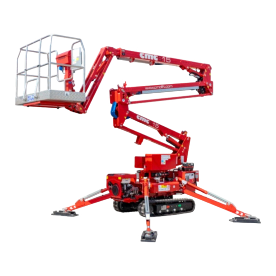
Page 16: General Machine Description
General Machine Description The MEWP series S15 MY2023 is an equipment intended for carrying opera- tors and working tools above ground. – The equipment has been designed with – All operations must be carried out by one innovative technologies and built by ap- of the properly trained and authorized plying integrated safety principles. - Page 17 quired to possess a certificate of qualifi- Danger - Warning cation issued by the competent authori- DO NOT use the equipment if the ties. wind speed is higher than 12,5 m/s – Training may be offered by technicians (45 km/h). authorised by the Manufacturer or by re- sponsible authorities.
-
Page 18: Description Of The Main Components
Description of the main components English language Tracked mobile elevating work platform... - Page 19 A) Undercarriage N) fuel tank – Refer to undercarriage user’s manual for P) Battery: powers the electric system. more information. Q) Engine operating controls B) Outriggers Note: The control panel varies ac- – The outriggers are activated inde- cording to the type of installed endo- pendently by hydraulic system.
-
Page 20: Basket Description
Basket description English language Tracked mobile elevating work platform... - Page 21 A) Basket can lift two operators and E) Step lock: it is used to lock the step D in their working tools.: “closed” position. Important Important The max. load in the basket SHALL When working, step D must be locked NOT exceed the maximum allowed in “closed”...
-
Page 22: Reasonably Foreseeable Wrong Use
Reasonably foreseeable wrong use The non-compliance with the informa- – NEVER disconnect the safety harness tion provided herein may lead to risks system during work, but only when the for the safety and health of the persons basket is in its stowed configuration. involved and may also lead to economic –... -
Page 23: Residual Risks
Due to the “sail” effect, the risk increas- – DO NOT service the equipment if it has es even if the wind speed is lower than not been stopped in safe conditions. the recommended limit. – DO NOT smoke while carrying out oper- –... -
Page 24: Guards And Safety Devices
Guards and safety devices The machine is equipped with safety de- vices that reduce the risks during the man-machine interaction. A) Emergency stop button.: Safety control – The emergency stop shall be performed to stop the parts the operation of which ONLY with a voluntary action on the emer- could imply safety risks. - Page 25 – The control must remain “locked” until nor- – (Red) steady indicator light: overload in mal operating conditions have been re- the basket higher than 20 kg. stored. Important – After the operating conditions have been The equipment movements are blocked restored, unlock the button to authorise until the overload in the basket is re- restart.
-
Page 26: Position Of Safety And Information Signals (Left Side)
Position of safety and information signals (left side) The figure shows the position of the sig- See “Description of the safety and in- nals. formation signals” English language Tracked mobile elevating work platform... - Page 27 Tracked mobile elevating work platform English language...
-
Page 28: Position Of Safety And Information Signals (Right Side)
Position of safety and information signals (right side) The figure shows the position of the sig- See “Description of the safety and in- nals. formation signals” English language Tracked mobile elevating work platform... - Page 29 Tracked mobile elevating work platform English language...
-
Page 30: Description Of The Safety And Information Signals
Description of the safety and information signals – Please keep safety signs and informa- be replaced and repositioned in the tion legible and follow the instructions. same place of origin. Note: To clean the signs use a cloth – The figures show safety signs and infor- soaked in a mix of warm water and mation with the corresponding descrip- cleanser. - Page 31 Tracked mobile elevating work platform English language...
-
Page 32: Technical Data Of Machine
Technical data of machine English language Tracked mobile elevating work platform... - Page 33 Unit of Description measure- Value ment Performance Max. work height mm (“) 14900 (586) Max. work outreach (rotating basket). - With one operator working in the basket mm (“) 7200 (284) - With 2 operators working in the basket mm (“) 7200 (284) Max.
-
Page 34: Technical Data Of Honda Engine
Technical data of Honda engine Unit of Value Description measure- GX390 iGX390 ment Manufacturer Honda Honda GX390 iGX390 Model 4-stroke 4-stroke Cooling Forced-air Forced-air Number of cylinders n° Displacement cm³ Piston bore and stroke Ø88 x 64 Ø88 x 64 Net power (at 3600 rev/min) kW (HP) 8,7 (11,7) -
Page 35: Electric Motor Technical Data
Electric motor technical data Unit of Value Description measure- 110 V 120 V 230 V ment MT Motori VALTARO Manufacturer CIMA Elettrici MOTORI Model 100M/4 XN100A/4 35 MM90L4 Output kW (HP) 2,2 (2,9) 1,6 (2,1) 2,2 (2,9) Voltage Amperage 20,7 15,1 Frequency Maximum number of... -
Page 36: Max. Reactions At Ground With Max
Max. reactions at ground with max. load English language Tracked mobile elevating work platform... -
Page 37: Operating Diagram
Operating diagram Tracked mobile elevating work platform English language... -
Page 38: Admitted Slopes
Admitted slopes – ALWAYS adapt the driving speed of the Important machine to the ground conditions and The shown values ARE NOT TO BE drive with maximum caution. considered as “safe limits”. The values are calculated consider- ing the equipment on compact and stable ground without any depres- sion and under favourable environ- mental conditions. -
Page 39: Areas Of Danger
Areas of danger The figure shows the dangerous areas during standard operation. Note: Immediately stop the machine access the dangerous areas and send operation if non-authorised people them away. Safety distance from power supply lines Danger - Warning NEVER touch the powered supply lines. Safety distance Rated voltage (kV) From 0 to 0,3... -
Page 40: Wind Speed
Wind speed The use with strong wind can cause the Note: Use a certified anemometer to stability loss of the equipment. measure the wind speed and direc- tion. – Do NOT hang elements that may in- crease the wind load (panels, flags, etc.) –... -
Page 41: Life Limits
Life limits – The aerial platform must be tested every Important 40000 load cycles. Structural electromechanical Note: The total cycles can corre- tests that must be carried out by the spond for example to 10 years, 40 Manufacturer or by authorised assis- weeks per year, 20 hours per week, 5 tance centres. -
Page 42: Endothermic Engine Controls Honda
Endothermic engine controls Honda English language Tracked mobile elevating work platform... - Page 43 A) Engine ignition key F) Indicator light (green): When on, it shows that the electric system has been – OFF) Engine switched off (removable activated. key ) G) Indicator light (red): When on, it shows – ON) Activated electrical system that alternator for battery charge is –...
-
Page 44: Endothermic Engine Controls Kubota
Endothermic engine controls Kubota English language Tracked mobile elevating work platform... - Page 45 A) Engine ignition key G) Indicator light (red): When on, it shows that engine oil pressure is not sufficient. – 0) Engine switched off (removable key ) H) Indicator light (red): When on, it shows – 1) Activated electrical system that coolant temperature is high.
-
Page 46: Control Console
Control console English language Tracked mobile elevating work platform... - Page 47 A) Joystick (non-release hold control) H) Selector: Outrigger overturn-restraint. – 1) Left track forward travel – a) Rear outriggers - With stabilized equipment: Basket an- – b) Front outriggers ti-clockwise rotation (optional) L) Emergency stop button.: Safety con- - When selector P is in position “a”.: trol to stop the parts the operation of Basket levelling which could imply safety risks.
-
Page 48: Outrigger Controls
Outrigger controls A) Lever (optional): control used to – The emergency stop shall be performed change the track axis distance. ONLY with a voluntary action on the emergency button. B) Lever: Outrigger “1”. – The control must remain “locked” until C) Lever: Outrigger “2”. - Page 49 Tracked mobile elevating work platform English language...
-
Page 50: Basket Controls
Basket controls English language Tracked mobile elevating work platform... - Page 51 A) Joystick (non-release hold control) H) Button: activation of endothermic en- gine. – 1) Basket anti-clockwise rotation – 2) Basket clockwise rotation L) Button: activation of electric motor. M) Button: basket levelling (counter-clock- B) Joystick (non-release hold control) wise rotation). –...
-
Page 52: Emergency Controls
Emergency controls English language Tracked mobile elevating work platform... - Page 53 A) Solenoid valve (non-release hold con- – The control must remain “locked” until trol) normal operating conditions have been restored. – Basket levelling – After the operating conditions have been B) Solenoid valve (non-release hold restored, unlock the button to authorise control) restart.
-
Page 54: Warning Indicator Light
Warning indicator light English language Tracked mobile elevating work platform... - Page 55 A) Indicator light (green): when on, it L) Indicator light (green): when on, it sig- shows that the outriggers are in proper nals that the pantograph system is closed. position. The indicator light must stay on until the M) Indicator light (green): when on, it sig- equipment is stabilised.
-
Page 56: Endothermic Engine Start-Up And Stop Honda
Endothermic engine start-up and stop Honda Start-up placed to position “OFF”. – Wait at least one minute between the dif- 1. Insert the key A and turn it clockwise to ferent attempts in order to cool down the position “ON”. starter. -
Page 57: Endothermic Engine Start-Up And Stop Kubota
Endothermic engine start-up and stop Kubota The engine does not start on a first at- Start-up tempt 1. Insert the key A and turn it clockwise to – Do not make too many attempts in a rap- position “1”. id sequence in order not to damage the –... -
Page 58: Electric Motor Start-Up And Stop
Electric motor start-up and stop Start-up Important 1. Connect power supply plug A. ONLY switch off the engine in stowed 2. Start the electric motor with selector B in configuration position “a” (or press button C). 2. Stop the electric motor with selector B in position “c”... -
Page 59: Emergency Stop And New Start-Up
Emergency stop and new start-up 1. In the presence of an imminent risk press 3. After the operating conditions have one of emergency buttons A-B-C-D. been restored, unlock the button to au- thorise restart. – All moving devices immediately stop. –... -
Page 60: Equipment Travelling (On Site)
Equipment travelling (on site) 1. Start the engine. Caution - Precaution 2. Lift the outriggers by using the ground The operator that carries out travel controls. MUST remotely follow the equipment 3. Properly wear the travelling control con- from a safe position. sole Note: Drive the machine in a prudent... -
Page 61: Spacing Of Track Axis Distance
Spacing of track axis distance Widening of track axis distance Narrowing of track axis distance 1. Position the equipment in its transport 1. Position the equipment in its transport configuration. configuration. 2. Move the equipment forwards and, at 2. Move the equipment forwards and, at the same time, use joystick A in direc- the same time, use joystick A in direc- tion “1”. -
Page 62: Stabilisation And Retraction Of Outriggers (Standard)
Stabilisation and retraction of outriggers (standard) Stabilization outrigger controls must ALWAYS be upstream from the slope. 1. Start the engine. 3. Make sure that there are no naked 2. Position the equipment in the foreseen flames or other heat sources in proximi- operating area. -
Page 63: Outriggers Retraction
4. Check the geomorphologic conditions of 10. Check the basket levelling. the soil (bearing capacity, slipping, level- Note: To restore basket levelling, ad- ling degree, water presence, etc.). just console controls. 11. During stabilization, check that all move- Important In case of loose soil, apply reinforce- ments are smooth and without unusual ment plates to the outriggers in order noises. -
Page 64: Stabilization And Retraction Of Outriggers (Automatic)
Stabilization and retraction of outriggers (automatic) Stabilization 4. Check the geomorphologic conditions of the soil (bearing capacity, slipping, level- 1. Start the engine. ling degree, water presence, etc.). 2. Position the equipment in the foreseen operating area. Important In case of loose soil, apply reinforce- 3. -
Page 65: Outriggers Retraction
5. Check whether there are any under- 11. Check for oil leaks, fluid leaks or other ground channels (water, gas, high pres- abnormal events. sure fluid ducts), elements under pres- Caution - Precaution sure and other sources of danger. DO NOT use the equipment before 6. -
Page 66: Basket Lifting And Retraction
Basket lifting and retraction Basket lifting Note: The max. load in the basket SHALL NOT exceed the maximum al- 1. Start the engine. lowed limit signalled by the switching 2. Load all tools necessary for work activity on of indicator light. in the basket. -
Page 67: Basket Retraction
The operators must wear also the 8. Use basket controls to lift it and to reach PPE according to the workplace safe- the desired position. ty laws in force. Note: Avoid that the outreach ex- ceeds the admitted value signalled by 3. -
Page 68: Basket Disassembly And Assembly
Basket disassembly and assembly During operations the equipment must be in transport configuration and on a stable and flat surface. Basket disassembly 2. Turn off the engine and remove the igni- tion key. 1. Slightly lift basket A. 3. Connect a lifting device to the basket A. Note: This operation facilitates the extraction of the pin C. -
Page 69: Basket Assembly
Note: To facilitate the extraction of 2. Turn off the engine and remove the igni- the pin C, keep the lifting device ten- tion key. sioned. 3. Connect a lifting device to the basket A. 4. Move the basket A to a position corre- 4. -
Page 70: Loading And Unloading For Transport
Loading and unloading for transport 1. Park the means of transport near the Important equipment or the embankment ramp. Carry out loading ONLY when the 2. Narrow track width (See “Spacing of equipment is in travelling direction. track axis distance”). Carry out unloading ONLY when the equipment is in reverse travelling di- 3. -
Page 71: Ramp For Means Of Transport
– Carry out operation only by using a suit- able lifting sling bar. Ramp for means of transport – The ramp must have suitable carrying – The operator MUST slowly control the capacity and dimensions. equipment from a correct safety dis- tance. -
Page 72: Equipment Lifting
Equipment lifting – DO NOT try to bypass the handling – Position the equipment in its transport configuration. modes and the points provided for lifting. Important – Slowly lift the equipment and carefully The personnel in change must have move it in order to avoid any dangerous expertise in the use of lifting devices. -
Page 73: Emergency Operations
Emergency operations Basket recovery in emergency mode – Equipment recovery with electric pump can be performed only in the following - “Basket recovery with electric pump” situations. - “Retraction of outriggers with electric pump” – “Basket recovery by the ground-level “Equipment transfer with electric operator”... -
Page 74: Basket Recovery By The Ground-Level Operator
Basket recovery by the ground-level operator – The operator working in the basket has 4. The operator at ground level activates pressed emergency stop button A but the control console D to move the bas- he/she is not able to unlock it. ket to its rest configuration. -
Page 75: Basket Recovery Due To The Failure Of The Hydraulic System
Basket recovery due to the failure of the hydraulic system. – If the hydraulic system is damaged, the 4. The operator must activate the basket ground-level operator must collaborate controls D in order to return it to its with the one in the basket. stowed configuration. -
Page 76: Basket Recovery Due To The Failure Of The Electric System
Basket recovery due to the failure of the electric system. 5. The operator must activate the basket – If the electric system is damaged, the controls D in order to return it to its ground-level operator must collaborate stowed configuration. with the operator working in the basket. -
Page 77: Hydraulic And Electric System Damaged
Hydraulic and electric system damaged – To recover the basket activate the emer- – Alternatively, the electric pump B pow- gency pump. ered by the battery of equipment can be required. – In its standard version, the pump is of “Basket recovery with electric manual type A. -
Page 78: Basket Recovery With Manual Pump
Basket recovery with manual pump The operations must be carried out in Note: The presence of an assistant is the sequence shown by the ground op- required to carry out some support erator. operations. 1. Disassemble the guard A. Note: In order not to slow down oper- ations too much, activate the controls 2. -
Page 79: Retraction Of Outriggers With Manual Pump
Retraction of outriggers with manual pump 1. Make sure that the aerial part of the Caution - Precaution equipment is in its rest position. DO NOT stand near the tracks to 2. Disassemble the guard E. avoid the risk of crushing lower 3. -
Page 80: Equipment Transfer With Manual Pump
Equipment transfer with manual pump This operation is necessary to position the equipment in a suitable area in order to load it onto the emergency vehicle. English language Tracked mobile elevating work platform... - Page 81 1. Disassemble the guard E. 8. Check whether the repair can be carried out on site. 2. Remove the safety seal of the valves P-Q. – For specialised operations move the equipment in an area equipped for re- 3. Extract spacers R-S. pair operations.
-
Page 82: Basket Recovery With Electric Pump
Basket recovery with electric pump The supplied pump is manual, but elec- The operations must be carried out in the tric pump A powered by the equipment sequence shown by the ground operator. battery may be required. Note: The presence of an assistant is required to carry out some support Important operations. -
Page 83: Retraction Of Outriggers With Electric Pump
Retraction of outriggers with electric pump 1. Make sure that the aerial part of the Important equipment is in its rest position. During the activation of the outrig- 2. Disassemble the guard D. gers avoid any excessive inclination 3. Rotate valve C to position “b”. of the equipment. -
Page 84: Equipment Transfer With Electric Pump
Equipment transfer with electric pump This operation is necessary to position the equipment in a suitable area in order to load it onto the emergency vehicle. 1. Disassemble the guard D. 8. Check whether the repair can be carried out on site. 2. - Page 85 Tracked mobile elevating work platform English language...
-
Page 86: Engine Start-Up With Emergency Battery
Engine start-up with emergency battery If the engine does not start up due to the battery, proceed as follows. English language Tracked mobile elevating work platform... - Page 87 1. Deactivate the connection to the battery 7. Start the engine. A by means of the battery switch device 8. Leave the equipment engine on. 9. Disconnect terminal E and terminal G. 2. Disassemble the guard C. 10. Disconnect terminal D and terminal F. 3.
-
Page 88: Refuelling
Refuelling Refilling must be carried out while the Caution - Precaution equipment is parked in a flat area and Do not smoke during refilling or when the engine is OFF. standing in that area. 1. Clean the intervention area from all res- 5. -
Page 89: Stop In Case Of Prolonged Inactivity
Stop in case of prolonged inactivity When the machine is expected to re- – Place the machine in a sheltered place main inactive for an extended period, that can be accessed only by authorised carry out the listed operations. people. Note: During operations the equip- –... -
Page 90: Recommendations For Maintenance
Recommendations for maintenance interventions – Read “Safety instructions for adjust- – DO NOT perform any interventions other ment and maintenance” in order to than those specified in the “Instructions find useful information. for use” without explicit authorization of the Manufacturer. –... - Page 91 Maintenance every 8 hours or one operation day Paragraphs to be read and/or Component Operation to be performed operating modes - Remove any oil and grease - Clean the walk-over flooring residues in order to avoid any risk of slipping. - Visually check any presence of drilling, abrasions and Basket...
- Page 92 Maintenance every 120 work hours (max 1 month) Paragraphs to be read and/or Component Operation to be performed operating modes - Tighten the fasteners. - Visually check any presence of wear, abrasions and - Check the general and cracks, etc. Cable chain integrity condition In case of damage refer to...
- Page 93 Maintenance after 400 hours (after first operation) Paragraphs to be read and/or Component Operation to be performed operating modes Hydraulic system oil - “Change of hydraulic system - Replace the filter filter oil filters” The operation must be carried out by the - Check the play between the Telescopic boom Manufacturer’s Assistance...
-
Page 94: Lubrication Point Diagram
Lubrication point diagram The frequency of the operations refer to the Manufacturer or lubricants with the actual operating hours. similar chemical-physical features. Important See “Lubricants and hydraulic oil” Use the lubricants recommended by for further details. English language Tracked mobile elevating work platform... -
Page 95: Lubricants And Hydraulic Oil
Lubricants and hydraulic oil Use the lubricants recommended by the Manufacturer or lubricants with similar chemical-physical features. Quantity Description Make and type Specifications lt (gallon) Gazpromneft Hydraulic Hydraulic HDZ ISO 32 / 64 40 (10.5) system oil BIOHYDRAN TMP 46 Engine oil Texaco Motor Oil S 5W-40 - Grease to... -
Page 96: Cleaning And Washing
Cleaning and washing Read paragraph “Recommendations Caution - Precaution for maintenance interventions” for use- DO NOT direct the water jets to elec- ful safety information. trical and electronic components to 1. Position the equipment in an area avoid any irreversible damage. equipped for operations in safe condi- tions. - Page 97 11. Activate telescopic boom by using con- Control of load limiting device trol console. 15. Load a weight corresponding to 250 kg The activated movement MUST stay (550 lbs) in the basket. stopped. 16. Start the engine. Note: If the movement is activated, 17.
- Page 98 Checking the emergency stop buttons 18. Start the engine. the ground-level operator must be in close proximity to the emergency con- – The operators must wear the PPE rec- trols. ommended in the “Instructions for use” and on the equipment. 19.
- Page 99 The movement MUST stop immediately. Note: If the movement is activated, contact the Technical Assistance Ser- Note: If the movement does not stop, vice of the Manufacturer. contact the Manufacturer’s Technical Assistance Service. 23. Release the emergency push-button to authorize restart of the machine. 22.
-
Page 100: Oil Tank Air Removal Mode
Oil tank air removal mode ALWAYS depressurize the tank before opening the filling cap. 1. Unscrew the cap A. 5. Disconnect the hose B from the pres- sure socket D. 2. Insert the end of the (supplied) hose B in a container C. -
Page 101: Check Of Hydraulic System Oil Level
Check of hydraulic system oil level 1. Position the equipment in an area - Stop the equipment, switch off the en- equipped for operations in safe condi- gine and remove the ignition key. tions. - Depressurize the tank B (See “Oil tank air removal mode”). -
Page 102: Change Of Hydraulic System Oil Filters
Change of hydraulic system oil filters 1. Position the equipment in an area 4. Let the engine cool down adequately to equipped for operations in safe condi- avoid being burnt. tions. 5. Disassemble the guard A. 2. Position the equipment in its transport 6. - Page 103 8. Loosen the cup C. 17. Check the oil level (See “Check of hy- draulic system oil level”). 9. Remove the oil filter unit B. 10. Overturn the oil filter unit B. Important 11. Remove cup C. DO NOT dispose of materials, pollut- ing liquids and waste generated dur- 12.
-
Page 104: Change Of Hydraulic System Oil
Change of hydraulic system oil 1. Position the equipment in an area 10. Insert a funnel into filling hole in order to equipped for operations in safe condi- add the oil correctly. tions. 11. Add the new oil until the correct level 2. -
Page 105: Problems, Causes, Remedies
Problems, causes, remedies The table shows the list of faults that can occur during the standard opera- tion and it highlights possible remedies. Problem Cause Remedy The equipment is in its - Position the equipment in transport configuration. its transport configuration. Light bulb damaged - Replace the light bulb. - Page 106 Problem Cause Remedy - Unlock the emergency stop Emergency stop button button with a voluntary activated action. The operation enabling pedal - Press the pedal to activate (optional) has not been the basket controls. activated. With stabilised equipment, - Replace the pump the controls in the basket This operation must be do not function.
- Page 107 Problem Cause Remedy - Unlock the emergency stop Emergency stop button button with a voluntary activated action. Flat battery - Recharge or replace battery After several attempts, the - Refill the tank with fuel. Fuel shortage endothermic engine does - See “Refuelling” not start - Check the oil level in the tank and, if necessary, fill it...
-
Page 108: Fuse Change
Fuse change 1. Position the equipment in an area 9. Disassemble the guard D. equipped for operations in safe condi- 10. Replace burnt fuse with another fuse tions. having the same features. 2. Stop the equipment, switch off the en- 11. -
Page 109: Disposal And Scrapping
Disposal and scrapping – DO NOT dispose of materials, polluting Decommissioning liquids and waste generated during op- – Sore the machine in a suitable area, not erations in the environment. of easy access and properly delimited in Carry out disposal according to the laws order to prevent it from being accessed. - Page 110 English language Tracked mobile elevating work platform...
- Page 111 Annexes...
- Page 112 – This manual may not replace any ade- structure is suitable for use through the quate experience that the operators inspection by specialised CMC techni- should have previously acquired with cians. similar equipment or that they may ac- –...
- Page 113 – TÜV SUD America Inc. is a OSHA recog- nised institute and a certification body – C.M.C. srl declares under own responsi- accredited by the Standards Council of bility that equipment “S15 MY2023” has Canada. been designed and build in compliance with the national and European regula-...
- Page 114 List of safety seals The safety components are calibrated Important and plunged in the Manufacturer’s facil- Restore all safety seals at the end of ities. repair operations. A) Equipment/outriggers exchange sole- Seals must be marked by an author- noid valve ised centre and replumbing must be B) Hydraulic control valves marked by the Manufacturer.
- Page 115 Overload tests When commissioning the equipment, – Tests must be performed only at the first the overload tests (with stabilised inspection of the equipment and they equipment) shown in the table were per- shall not be repeated. formed. Important – When commissioning, stability Tests with the same loads shall not be...
- Page 116 Operating tests When testing the equipment, the Manu- facturer performed the below tests. Test / component description Test result - Operation interruption when releasing the selected operating lever in control positions. - Basket levelling operation allowed only when the aerial part of the equipment is in its stowed configuration.
- Page 117 This table is used to record the replacement of the main com- ponents (mechanical, electrical, safety components, etc.). Check record table Place and Component code and/ Stamp and Replacement reason date or description signature Annexes English language...
- Page 118 This table is used to record the maintenance operations performed. Regular audit record table Place and Stamp and Operation description date signature English language Annexes...
- Page 119 Ownership certificate Annexes English language...
- Page 120 Hydraulic system diagram English language Annexes...
- Page 121 Admitted slopes 38 Electric motor start-up and stop 58 Areas of danger 39 Start-up 58 Stop 58 Electric motor technical data 35 Emergency controls 52 Basket controls 50 Emergency operations 73 Basket description 20 Emergency stop and new start-up 59 Basket disassembly and assembly 68 Endothermic engine controls Honda 42 Basket assembly 69...
- Page 122 Lubricants and hydraulic oil 95 Lubrication point diagram 94 Safety distance from power supply lines 39 Scheduled maintenance intervals 90 Spacing of track axis distance 61 Max. reactions at ground with max. load 36 Narrowing of track axis distance 61 Widening of track axis distance 61 Stabilisation and retraction of outriggers (standard) 62...
- Page 123 lingua italiana...
- Page 124 Via Bitritto, 119 - 70124 BARI - ITALY Tel. +39 080 532 66 06 - Fax +39 080 536 85 41 www.cmclift.com - info@cmclift.com...
Need help?
Do you have a question about the S15 MY2023 and is the answer not in the manual?
Questions and answers