
Related Manuals for CMC S32


Summary of Contents for CMC S32
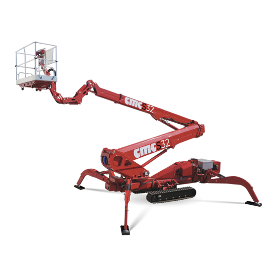
- Page 1 Use and maintenance manual MAN.218 Rev.8 ORIGINAL Mobile elevating work platform Brand C.M.C. Model S32...
-
Page 2: Content Of The Manual
➔ This manual is addressed to: ▪ users: operators, ground assistants, guard staff, safety manager, service manager; ▪ manufacturers, dealers, owners, lessors or lessee, brokers. MAN.218 Rev.8 ENG - Use and maintenance manual S32 page... - Page 3 ➔ This manual (or its copy) must always be on the machine (in a case near the turret) for an immediate consultation by the operator during working operations. MAN.218 Rev.8 ENG - Use and maintenance manual S32 page...
- Page 4 C.M.C. s.r.l. provisions, without being anyway obliged to intervene on the previously sold machines and on their manuals. MAN.218 Rev.8 ENG - Use and maintenance manual S32 page...
-
Page 5: Specifications
2,35 m 7.71 ft with tracks opened (G) Total width without basket 1,90 m 6.23 ft (G’) Total width with tracks closed, 1,56 m 5.12 ft boom extended, and basket coupled MAN.218 Rev.8 ENG - Use and maintenance manual S32 page... - Page 6 Max allowed rotation speed 0,7 m/s (2.3 ft/s) Max allowed manual force in the basket with 400 N 1 operator Tightening torque Bolts of the bearing M16 cl 10.9 28 daNm MAN.218 Rev.8 ENG - Use and maintenance manual S32 page...
- Page 7 MAN.218 Rev.8 ENG - Use and maintenance manual S32 page...
-
Page 8: Identification Plate
As for the displacement, it belongs to type 1: travelling is only allowed with the MEWP in its transport configuration or in the stowed position (EN 280 Picture 1: identification plate. par. 1.4 - ANSI/SAIA A92.20 par. 3). MAN.218 Rev.8 ENG - Use and maintenance manual S32 page... -
Page 9: Working Diagram
(valid only in the working area set by the outriggers placement). Loading cycle: a cycle starts from the access position, continues performing the work and finishes returning to the access position. MAN.218 Rev.8 ENG - Use and maintenance manual S32 page... - Page 10 Picture 3b: stabilization areas. MAN.218 Rev.8 ENG - Use and maintenance manual S32 page...
-
Page 11: Description And Purpose
Description and purpose Machine definition The machine is called S32 and it is a mobile elevating work platform (MEWP): • machine/device intended for moving persons, tools and material to working positions, consisting of at least a work platform with controls, an extending structure and a chassis (ANSI/SAIA 92.20... -
Page 12: Description Of The Main Components
Description of the main components Picture 3: MEWP main components. MAN.218 Rev.8 ENG - Use and maintenance manual S32 page... - Page 13 The extension (or withdrawal) of the telescopic boom is given by operating the “telescopic boom extension cylinder”. The lifting (or lowering) of the telescopic boom is given by operating the “lifting cylinder of second telescopic boom group”. MAN.218 Rev.8 ENG - Use and maintenance manual S32 page...
-
Page 14: Control Stations
(par. 4.6.1). 3.1.1 Ignition of the endothermic engine In order to start the endothermic engine, turn the IK key all the way to the right. MAN.218 Rev.8 ENG - Use and maintenance manual S32 page... - Page 15 (Picture 17). powered by 300 Ah lithium batteries or with a hybrid feed. The *optional platform control station is: • AUTEC radio control (Picture 13), instead of wired remote control station. MAN.218 Rev.8 ENG - Use and maintenance manual S32 page...
- Page 16 • two joysticks J1 and J2 for aerial part and crawlers’ operations; • a red mushroom-shaped emergency button EB (on the right side of the control station): it stops the machine de-energizing the electrical circuits; MAN.218 Rev.8 ENG - Use and maintenance manual S32 page...
- Page 17 Alarm light when reaching the maximum performance Alarm light when reaching the load limit Picture 11: central side of basket console. Endothermic engine switching on/off button Electric engine (*optional) switching on/off button MAN.218 Rev.8 ENG - Use and maintenance manual S32 page...
- Page 18 Platform wired/radio control station The switching on of the main standard wired AUTEC control station excludes the use of the basket control station. Picture 14: AUTEC wired remote control label. MAN.218 Rev.8 ENG - Use and maintenance manual S32 page...
-
Page 19: Home Button
– second boom extension – basket counterclockwise rotation (at right side) / backward travel of right track – second boom lowering – jib lowering (downward) Leveling “dead man” lever MAN.218 Rev.8 ENG - Use and maintenance manual S32 page... - Page 20 Destabilization/crawlers narrowing "dead man" button Through the control station in Picture 15, located on the right side of machine chassis, it is possible to perform stabilization/destabilization of the S32, to Stabilization/crawlers widening "dead man" button widen/tighten the tracks (par. 4.4.2.1), and enable/disable the use of the wired ON/OFF button to enable/disable wired remote control remote control station.
- Page 21 The functions of the different cursors will be described in the section on the Command Operation description recovery procedures of the aerial part (par. 4.5.3.1). 35/36 Selection button of menu options and data Enter menu button MAN.218 Rev.8 ENG - Use and maintenance manual S32 page...
-
Page 22: Use Procedures
Any addition that increases the wind load on the MEWP, such as warning signs, is prohibited. Do not operate when the wind speed exceeds 12,5 m/s (45 km/h). We hereby enclose “Beaufort wind scale” (Table 1): MAN.218 Rev.8 ENG - Use and maintenance manual S32 page... -
Page 23: Safety Distances
19° (34%). If you choose this way, please proceed with the following procedure, carefully reading the danger notes suggested. MAN.218 Rev.8 ENG - Use and maintenance manual S32 page... - Page 24 Ensure that the machine is switched off during the transport. Travel and climb with the MEWP set as shown in Picture 21: the basket shall always be placed at the rear of the machine. MAN.218 Rev.8 ENG - Use and maintenance manual S32 page...
- Page 25 6. Position the speed selector SS (Picture 22) on the central "turtle" "double hare": maximum speed. symbol; move it downward to “hare” symbol to increase the tracks speed or upward to “double hare” to reach the maximum speed. MAN.218 Rev.8 ENG - Use and maintenance manual S32 page...
- Page 26 2. make sure that the basket block pin is inserted (Picture 28); 3. make sure that the boom groups are perfectly retracted and supported; 4. disable the wired remote/radio control or disconnect it; MAN.218 Rev.8 ENG - Use and maintenance manual S32 page...
- Page 27 In case there are not such conditions, it is strictly forbidden to use the MEWP. 4. Place the MEWP on the chosen area. 5. Define the working area with appropriate signals (white-red ribbon, white-red chains, cones, etc.). MAN.218 Rev.8 ENG - Use and maintenance manual S32 page...
- Page 28 Picture 25: outriggers pin. remote/radio control: 7. With the pin lifted (Picture 25), rotate the outrigger taking it in a position which allows the reinsertion of the same pin. For each MAN.218 Rev.8 ENG - Use and maintenance manual S32 page...
- Page 29 C to block it to the jib support (Picture 28). 11. Enter the basket by lifting the self-locking closing bar and using the underlying step; ensure the bar is back to the closing position; MAN.218 Rev.8 ENG - Use and maintenance manual S32 page...
- Page 30 It is strictly forbidden to rotate the turret as first movement, since it could seriously damage the carpentry. It is forbidden to enter or exit the work platform at different levels, when the machine is developed. MAN.218 Rev.8 ENG - Use and maintenance manual S32 page...
- Page 31 IT IS ESSENTIAL TO CARRY OUT THE DESTABILIZATION BY OPERATING ON ALL FOUR LEVERS SIMULTANEOUSLY. Slowdowns can be set by software for start and end of each aerial part maneuver (lifting/lowering of booms, extension/retraction of booms, clockwise/ MAN.218 Rev.8 ENG - Use and maintenance manual S32 page...
-
Page 32: "Home" Function
Corresponding to: SOUND Continuous acoustic signal (intermittent in pre-alarm): Load limiter light activated on basket when exceeding console and on wired remote control. maximum load allowed. MAN.218 Rev.8 ENG - Use and maintenance manual S32 page... -
Page 33: Emergency Operations
2. on the center of the wired remote control station (Picture 13); 3. on the left side of the stabilizers control station (Picture 15); 4. on the left side of the turret distributor (Picture 19). MAN.218 Rev.8 ENG - Use and maintenance manual S32 page... - Page 34 • reach the main inlet group (Picture 32) on the frame and remove the During aerial part return operations, the operators should also carry out the leveling and the rotation of the basket: carter; MAN.218 Rev.8 ENG - Use and maintenance manual S32 page...
- Page 35 7: at left side to perform external leveling of the side of machine to enable stabilizers recovery maneuvers. basket and at the right side for internal leveling; MAN.218 Rev.8 ENG - Use and maintenance manual S32 page...
- Page 36 Unseal and screw the crawlers electrovalves (Picture 37), placed on the right side of machine, to enable tracks recovery maneuvers: o the left one corresponding to the left crawler; o the right one corresponding to the right crawler. MAN.218 Rev.8 ENG - Use and maintenance manual S32 page...
- Page 37 230/380 V auxiliary electrical engine *optional (par. 3.1.2); o the emergency electropump *optional (par. 4.5.6); o the manual pump (par. 4.5.5). Picture 38: travel workbench. MAN.218 Rev.8 ENG - Use and maintenance manual S32 page...
- Page 38 Before starting the recovery of the aerial part, turn the double tap on the A + D positions, as indicated by the marking applied near them (Picture 40). Then perform the aerial part recovery as described in paragraph 4.5.3.1. MAN.218 Rev.8 ENG - Use and maintenance manual S32 page...
-
Page 39: Safety Rules
MEWP. C.M.C. s.r.l. declines any responsibility coming from electropump tap (Picture 42), first to the bottom to recovery the aerial part and then to the top to recovery the outriggers. MAN.218 Rev.8 ENG - Use and maintenance manual S32 page... - Page 40 – by the user – of ➔ Stabilize the truck through the outriggers. the liabilities coming from an incorrect functioning of the safety devices. MAN.218 Rev.8 ENG - Use and maintenance manual S32 page...
- Page 41 It is strictly forbidden to level the basket when the machine is in working ➔ During works like paintings, etc., protect yourselves and the machine; position; Do not operate when the MEWP is in failure; MAN.218 Rev.8 ENG - Use and maintenance manual S32 page...
-
Page 42: Safety Devices
Do not intervene on your own safety devices. In case of tampering, the manufacturer declines all responsibility about any accidents attributable to these interventions. It is forbidden to leave the MEWP unattended when it is in working position; MAN.218 Rev.8 ENG - Use and maintenance manual S32 page... - Page 43 • Pressure relief valves for the protection of the entire hydraulic circuit and the individual parts of the system. • Block valve and parachute valve mounted on the lifting cylinders; MAN.218 Rev.8 ENG - Use and maintenance manual S32 page...
- Page 44 Before using the MEWP, it is compulsory to check the presence and the perfect readability of these marks. In case of absence or decay of the marks, contact the Service. Picture 45: work diagram. Picture 43: identification plate (fac-simile). MAN.218 Rev.8 ENG - Use and maintenance manual S32 page...
- Page 45 Picture 50: max capacity allowed in the basket. Picture 47: MOBA basket control station. Picture 51: load cell marking. Picture 52: safety belt attachment point. Picture 48: outriggers control station. MAN.218 Rev.8 ENG - Use and maintenance manual S32 page...
- Page 46 Picture 55: travel directions on tracks. Picture 56: maximum slopes for travel. Picture 60: maximum load on stabilizers. Picture 57: travel block bypass. Picture 61: prohibition to stand in work area. MAN.218 Rev.8 ENG - Use and maintenance manual S32 page...
- Page 47 Picture 70: indication for engine battery disconnection. Picture 65: danger of flammable substances. Picture 71: indication of platform fuse. Picture 66: indication for grease application. Picture 72: indication of frame coupling. MAN.218 Rev.8 ENG - Use and maintenance manual S32 page...
- Page 48 Picture 74: warning for basket operator fainting. Picture 77: emergency bypass. Picture 78: indication of emergency manual pump. Picture 75: emergency workbench on turret. Picture 79: aerial part/stabilizers exchange tap in case of manual pump. MAN.218 Rev.8 ENG - Use and maintenance manual S32 page...
- Page 49 Picture 81: general obligations and prohibitions. Picture 87: high pressure hazard. Picture 82: warning for tracks lifting during stabilization. Picture 88: danger of falling. Picture 83: warning of burn risk. MAN.218 Rev.8 ENG - Use and maintenance manual S32 page...
- Page 50 Picture 90: machine sound power. Picture 93: MEWP use guidelines. Picture 91: prohibition to wet the machine. Picture 92: warning to obligate to the consultation of use and maintenance manual. MAN.218 Rev.8 ENG - Use and maintenance manual S32 page...
- Page 51 Picture 94: compliance with ANSI and CAN/CSA rules. Picture 95: inspection tag. MAN.218 Rev.8 ENG - Use and maintenance manual S32 page...
-
Page 52: Electrical System
MEWP have been calibrated: a correct calibration of these parts (which is possible only in C.M.C. or in authorized Services) is important to assure the safety of the machine. MAN.218 Rev.8 ENG - Use and maintenance manual S32 page... -
Page 53: Hydraulic System
Normally, leaks on the pipes can be eliminated by correctly tightening the fittings. If leaks in the sealing areas (o-rings, sealing rings, etc.), the restoration of the seal can only be carried out by replacing the gasket. MAN.218 Rev.8 ENG - Use and maintenance manual S32 page... -
Page 54: Daily Maintenance
(presence of dust, sand, etc.), an optimal maintenance frequency is left to the good sense of the user. MAN.218 Rev.8 ENG - Use and maintenance manual S32 page... - Page 55 Operate the lever for the lift o Operate the lifting and MEWP. MEWP. lowering Contact Contact lowering lever of the telescopic outriggers. Service. Service. boom. OUTRIGGERS SHALL NOT MOVE. THE TELESCOPIC BOOM SHALL NOT MOVE. MAN.218 Rev.8 ENG - Use and maintenance manual S32 page...
-
Page 56: Weekly Maintenance
Service. Check the cleanliness of the hydraulic filters. C.M.C. Check that the blocking systems (pins, locknut, etc.) are in perfect condition and efficient. strictly forbidden C.M.C. MEWP. Contact the Service. MAN.218 Rev.8 ENG - Use and maintenance manual S32 page... -
Page 57: Annual Maintenance
Operations Replacement of the hydraulic filters (25 micron). USER / C.M.C. Complete check of the whole machine and note the USER / C.M.C. results in the appropriate manual section. MAN.218 Rev.8 ENG - Use and maintenance manual S32 page... -
Page 58: Safety Rules During Maintenance
MAN.218 Rev.8 ENG - Use and maintenance manual S32 page... - Page 59 Weight Interflon LUBE EP+ Composition: mixture of mineral and vegetable oils, additives and Dimension (L*W*H) 180x310x100 Teflon®. Density, 20°C: 0,89 g/cm3 Kinematic viscosity, 20°C (ASTM D2983): 380 mPa. MAN.218 Rev.8 ENG - Use and maintenance manual S32 page...
- Page 60 Many components of the MEWP have been calibrated: a correct calibration of these parts (which is possible only in C.M.C. or in authorized repair shops) is necessary to assure the safety of the machine. MAN.218 Rev.8 ENG - Use and maintenance manual S32 page...
- Page 61 2. Share your Internet wireless network with the remote connection device in free mode (without password); 3. Lift the connection remote switch on the chassis box covered by a carter on the right side of the machine (Picture 97): MAN.218 Rev.8 ENG - Use and maintenance manual S32 page...
-
Page 62: Troubleshooting
2. Replace the seals. Remedies: 1. Replace the hydraulic pump. If the problem persists, contact the Service. 2. Replace the stabilizers limit switches. ___________________________________________________________ If the problem persists, contact the Service. ___________________________________________________________ MAN.218 Rev.8 ENG - Use and maintenance manual S32 page... - Page 63 Service Centre, it is possible – at any moment – to detect and solve the problem. Contact our Service Centre for any technical problem which is not identified nor solved by the aforesaid procedure. MAN.218 Rev.8 ENG - Use and maintenance manual S32 page...
- Page 64 • proportional valves. The tampering or replacement of components by non-authorized staff is strictly forbidden. ➔ It is mandatory to restore the sealings after use of these items. MAN.218 Rev.8 ENG - Use and maintenance manual S32 page...
- Page 65 11 Overload tests During the commissioning of the machine, in the final test, we carried out the following overload tests. During it, we tested S32 stability and structural resistance. With the machine at maximum working outreach, test loads are added to nominal load to perform mechanical evaluations and to obtain product certifications.
-
Page 66: Operating Tests
▪ Electropump (*optional). During the commissioning of the machine, we carried out the following final operation tests. We have tested the correct operation of the S32 and of its safety systems. Test description Outcome ▪ Block of the operation in case of release of the selected operation lever. -
Page 67: Control Register
Replacement of electrical components (par. 13.6) ➢ Replacement of safety devices (par. 13.7) ➢ Considerable failures and relevant repairs (par. 13.8) ➢ Periodical checks and maintenance journal (par. 13.9) ➢ Notes (par. 13.10) MAN.218 Rev.8 ENG - Use and maintenance manual S32 page... - Page 68 The seller The buyer The seller The buyer MAN.218 Rev.8 ENG - Use and maintenance manual S32 page...
- Page 69 Place …………………. Date ……………….… Stamp and signature of the responsible Stamp and signature of the responsible for the firm in charge The user for the firm in charge The user MAN.218 Rev.8 ENG - Use and maintenance manual S32 page...
- Page 70 Place …………………. Date ……………….… Stamp and signature of the responsible Stamp and signature of the responsible for the firm in charge The user for the firm in charge The user MAN.218 Rev.8 ENG - Use and maintenance manual S32 page...
- Page 71 Place …………………. Date ……………….… Stamp and signature of the responsible Stamp and signature of the responsible for the firm in charge The user for the firm in charge The user MAN.218 Rev.8 ENG - Use and maintenance manual S32 page...
-
Page 72: Replacement Of Electrical Components
Place …………………. Date ……………….… Stamp and signature of the responsible Stamp and signature of the responsible for the firm in charge The user for the firm in charge The user MAN.218 Rev.8 ENG - Use and maintenance manual S32 page... - Page 73 Place …………………. Date ……………….… Stamp and signature of the responsible Stamp and signature of the responsible for the firm in charge The user for the firm in charge The user MAN.218 Rev.8 ENG - Use and maintenance manual S32 page...
- Page 74 Place…………………. Date………………….……….… Place…………………. Date………………….……….… Stamp and signature of the responsible Stamp and signature of the responsible for the firm in charge The user for the firm in charge The user MAN.218 Rev.8 ENG - Use and maintenance manual S32 page...
- Page 75 13.9 Periodical checks maintenance register DATE SERVICE SIGNATURE ➔ The user shall observe the maintenance and control program described in this manual. DATE SERVICE SIGNATURE MAN.218 Rev.8 ENG - Use and maintenance manual S32 page...
- Page 76 DATE SERVICE SIGNATURE DATE SERVICE SIGNATURE MAN.218 Rev.8 ENG - Use and maintenance manual S32 page...
- Page 77 ………………………………………………………………………………………….. ………………………………………………………………………………………….. ………………………………………………………………………………………….. ………………………………………………………………………………………….. ………………………………………………………………………………………….. ………………………………………………………………………………………….. ………………………………………………………………………………………….. ………………………………………………………………………………………….. ………………………………………………………………………………………….. ………………………………………………………………………………………….. ………………………………………………………………………………………….. ………………………………………………………………………………………….. ………………………………………………………………………………………….. ………………………………………………………………………………………….. ………………………………………………………………………………………….. ………………………………………………………………………………………….. ………………………………………………………………………………………….. ………………………………………………………………………………………….. ………………………………………………………………………………………….. ………………………………………………………………………………………….. ………………………………………………………………………………………….. ………………………………………………………………………………………….. ………………………………………………………………………………………….. ………………………………………………………………………………………….. ………………………………………………………………………………………….. ………………………………………………………………………………………….. ………………………………………………………………………………………….. ………………………………………………………………………………………….. ………………………………………………………………………………………….. ………………………………………………………………………………………….. MAN.218 Rev.8 ENG - Use and maintenance manual S32 page...
- Page 78 Lithium battery pack recharge (*optional) 31 Periodical checks and maintenance register 74 13.9 Emergency operations 32 13.10 Notes 76 Safety rules 38 Safety devices 41 43 5Markings 6Electrical system 51 MAN.218 Rev.8 ENG - Use and maintenance manual S32 page...
Need help?
Do you have a question about the S32 and is the answer not in the manual?
Questions and answers