Table of Contents
Advertisement
Quick Links
Advertisement
Table of Contents

Subscribe to Our Youtube Channel
Related Manuals for CMC S28


Summary of Contents for CMC S28
- Page 1 USE AND MAINTENANCE MANUAL Man.243 Rev.5 Mobile Elevating Work Platform(MEWP)
- Page 2 MAN.243 Rev.5 ENG - Use and maintenance manual S28 page...
-
Page 3: Content Of The Manual
❑ show the main specifications of the machine; ❑ provide with the instructions for the positioning and use of the machine; ❑ describe the safety devices; MAN.243 Rev.5 ENG - Use and maintenance manual S28 page... - Page 4 * (OPTIONAL) = it indicates an optional outfit. MAN.243 Rev.5 ENG - Use and maintenance manual S28 page...
- Page 5 All other languages are copies of the original The operator shall carefully know the safety instructions. standards foreseen by national and international legislations and apply them during all operations with the MEWP. MAN.243 Rev.5 ENG - Use and maintenance manual S28 page...
- Page 6 European standard EN280 1418.10-2011 which provides the presumption of conformity + A1-2017 to Essential Safety Requirements of the Machinery Directive 2006/42/EC being Voluntary Technical Standard - type C; MAN.243 Rev.5 ENG - Use and maintenance manual S28 page...
- Page 7 C.M.C. to receive supplementary technical documents. No part of this publication can be translated, modified or reproduced (even partially) without the expressed authorization of C.M.C. s.r.l. Year 2021 C.M.C. s.r.l. MAN.243 Rev.5 ENG - Use and maintenance manual S28 page...
-
Page 8: Description And Purpose
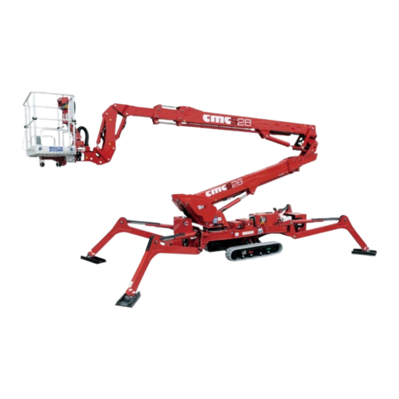
1.1 Machine definition vertical use. It must be travelled only when it is totally folded in the transport position. The machine is called S28 and it is a mobile ➔ elevating work platform (MEWP): The use of the machine is allowed only to •... -
Page 9: Tüv Certification
As for the displacement, it belongs to type 1: travelling is only allowed with the MEWP in its transport Loading cycle: a cycle starts from the access position, continues performing the work and finishes returning to the access position. MAN.243 Rev.5 ENG - Use and maintenance manual S28 page... -
Page 10: Identification Plate
1.7 Identification plate On the turret, there is a plate with (engraved) all the MEWP identification data: Picture 1: identification plate (fac-simile). MAN.243 Rev.5 ENG - Use and maintenance manual S28 page... -
Page 11: Specifications
6.54/7.19 ft tracks widened (front/rear) (with tracks Max. slope approach angle with narrowed/widened) 7°-10°/12%-18% tracks narrowed (front/rear) Total width 0,90 m 2.95 ft Max. slope to travel (without basket) 19°-8°/34%-14% (longitudinally/transversally) MAN.243 Rev.5 ENG - Use and maintenance manual S28 page... - Page 12 Outrigger spread width in 2,67 m 8.76 ft narrow stabilization area Outrigger spread width in 3,63 m 11.91 ft mixed stabilization area Outriggers foot diameter Ø 0,24 m 0.79 ft MAN.243 Rev.5 ENG - Use and maintenance manual S28 page...
- Page 13 0,7 m/s (2.3 ft/s) Max. manual force in the basket 400 N with 1 operator Bolts Size Tightening torque Slewing ring M16 cl 10.9 28 daNm Geared motor M16 cl 10.9 28 daNm MAN.243 Rev.5 ENG - Use and maintenance manual S28 page...
- Page 14 MAN.243 Rev.5 ENG - Use and maintenance manual S28 page...
- Page 15 2.2 Work diagram Picture 2a: work diagram (valid only in the work area set by the outriggers placement). MAN.243 Rev.5 ENG - Use and maintenance manual S28 page...
- Page 16 Picture 2b: work areas. MAN.243 Rev.5 ENG - Use and maintenance manual S28 page...
-
Page 17: Description Of The Main Components
2.3 Description of the main components Picture 3: MEWP main components. MAN.243 Rev.5 ENG - Use and maintenance manual S28 page... - Page 18 “lifting cylinder of second telescopic 2.3.3 First telescopic boom group boom group”. The first telescopic boom group 6 (Picture 3) is composed by three elements: a fixed boom and two extendable booms. MAN.243 Rev.5 ENG - Use and maintenance manual S28 page...
- Page 19 The floor is in antiskid and auto-draining aluminum. The basket is connected to a support 9 (Picture 3) through which it is coupled with the jib. MAN.243 Rev.5 ENG - Use and maintenance manual S28 page...
- Page 20 Picture 4: engine switch on/off station. ignition key all the way to the right up to the symbol The main electric box (Picture 4), located on the right side of the frame, provide: MAN.243 Rev.5 ENG - Use and maintenance manual S28 page...
- Page 21 Using the radio control: • turn the key to position 1; Picture 6: power on/off lever on the radio control. • connect the radio control (link procedure in par. 3.2.2), MAN.243 Rev.5 ENG - Use and maintenance manual S28 page...
- Page 22 To switch off the electric motor, it will be enough to alternatively: • turn the key all the way to the left on position 0; • lower the lever mentioned above (Picture 6) of the radio control; MAN.243 Rev.5 ENG - Use and maintenance manual S28 page...
- Page 23 The start and stop of the 48 V electric motor will be the same shown above for 110/120/230 V electric motor. MAN.243 Rev.5 ENG - Use and maintenance manual S28 page...
- Page 24 Picture 7b: transformer box* with voltage selector. The *optional platform control stations are: This allows you to have electrical outlets of both voltages (Picture 7c): on the ground to power the electric motor MAN.243 Rev.5 ENG - Use and maintenance manual S28 page...
- Page 25 EB (on the right side of the control station): it stops the machine de-energizing the electrical circuits. The emergency button has an auto-detent mechanical locking system; therefore, it is MAN.243 Rev.5 ENG - Use and maintenance manual S28 page...
- Page 26 • a series of control buttons/lights described in the following table. Picture 10: left side of basket console. MAN.243 Rev.5 ENG - Use and maintenance manual S28 page...
- Page 27 Picture 11: central side of basket console. Picture 12: right side of basket console. The basket control station (*optional) allows the following maneuvers: MAN.243 Rev.5 ENG - Use and maintenance manual S28 page...
- Page 28 Alarm LED warning: maximum load limit clockwise rotation of the basket reached Stabilization consent light LED Endothermic engine switch on/off button Aerial part use consent light LED Electric engine (*optional) on/off button MAN.243 Rev.5 ENG - Use and maintenance manual S28 page...
- Page 29 Radio control link procedure: described below (radio control activation directly excludes the basket control station). To connect the radio control, press the green Start/Link button SL (Picture 14) down on the left side. MAN.243 Rev.5 ENG - Use and maintenance manual S28 page...
- Page 30 MAN.243 Rev.5 ENG - Use and maintenance manual S28 page...
- Page 31 MAN.243 Rev.5 ENG - Use and maintenance manual S28 page...
- Page 32 Picture 16: AUTEC radio control decal. MAN.243 Rev.5 ENG - Use and maintenance manual S28 page...
- Page 33 On/off lever: upward for endothermic If the battery of the AUTEC radio control is low, it could engine and downward for auxiliary become a wired remote control, by connecting the electric engine (*optional). MAN.243 Rev.5 ENG - Use and maintenance manual S28 page...
- Page 34 3.2.2.1 AUTEC radio control display Moreover, this station has a color display (Picture 18) which allows to visualize all the function parameters of the machine. Picture 19: “Key Off” screen. MAN.243 Rev.5 ENG - Use and maintenance manual S28 page...
- Page 35 "Home" screen (Picture 20). In this screen, with the machine closed, the green consent led TRACKS is on for the use of the tracks during the machine travel. MAN.243 Rev.5 ENG - Use and maintenance manual S28 page...
- Page 36 - RL (rear left) will change from red to green; the consent light PLATF for use of the aerial part turn on, simultaneously with the turning off of the consent light TRACKS for use of tracks. Picture 22: Chassis C1-C2 screens. MAN.243 Rev.5 ENG - Use and maintenance manual S28 page...
- Page 37 - boom 1 resting on a support; - monitored electro valve of the outriggers. Picture 23: Chassis C3-C4 screens. In the screens C3 and C4 (Picture 23), related to the "Chassis output", you can monitor: MAN.243 Rev.5 ENG - Use and maintenance manual S28 page...
- Page 38 In the A1 screen there are the values related to: - length and angles of the booms; - angles of jib, basket and turret; MAN.243 Rev.5 ENG - Use and maintenance manual S28 page...
- Page 39 Picture 26: T screen. In the A2, A3 and A4 screens (Picture 25), you can read the data in input and output of the system: - centering of the basket; MAN.243 Rev.5 ENG - Use and maintenance manual S28 page...
- Page 40 In the screens from T1 to T14 (Picture 27), you can view a glossary of all errors that may appear on the display, with corresponding codes and descriptions. Picture 28: T15 screen. MAN.243 Rev.5 ENG - Use and maintenance manual S28 page...
- Page 41 In the T26 screen (Picture 29), the display language can be selected. Picture 30: T27-T28 screens. In T27-T28 screens (Picture 30), the units of measurement for weights and lengths can be selected among European and US measurement systems. MAN.243 Rev.5 ENG - Use and maintenance manual S28 page...
- Page 42 The password can be inserted only by the manufacturer CMC or the authorized workshop staff. The following operations must be made after CMC authorization and under the supervision of trained and specialized staff. MAN.243 Rev.5 ENG - Use and maintenance manual S28 page...
- Page 43 MAN.243 Rev.5 ENG - Use and maintenance manual S28 page...
- Page 44 The T21-T22 (Picture 36) screens show the values of the angle sensors are visualized: their sensor calibration can two jib angle sensors and the two basket angle sensors: be reset. it is possible to reset the sensor calibration. MAN.243 Rev.5 ENG - Use and maintenance manual S28 page...
- Page 45 Picture 37: T23-T24 screens. In T23-T24 screens (Picture 37), there are the values of the two lower boom length sensors and the two upper boom length sensors: their sensor calibration can be reset. MAN.243 Rev.5 ENG - Use and maintenance manual S28 page...
- Page 46 (par. 4.4.2.1). The machine in travel position is meant with the basket on the rear. MAN.243 Rev.5 ENG - Use and maintenance manual S28 page...
- Page 47 MEWP aerial part. Picture 40: distributor in the emergency workbench. The functions of the different cursors will be described in the section on the recovery procedures of the aerial part (par. 4.5.3.1). MAN.243 Rev.5 ENG - Use and maintenance manual S28 page...
-
Page 48: Use Procedures
(after having Do not operate in areas with dangerous controlled their integrity) and any other Protective environmental conditions: poor visibility, storms, lightning risk, etc. MAN.243 Rev.5 ENG - Use and maintenance manual S28 page... - Page 49 In order to load/unload the platform, it is possible to use a travelling crane of adequate capacity. Sling the MEWP by the connections on the frame (Picture 41). Table 1: Beaufort wind scale. Picture 41: couplings on the frame. MAN.243 Rev.5 ENG - Use and maintenance manual S28 page...
- Page 50 (i.e. galleries, the machine tracks. bridges, electrical and phone lines, etc.). Check that the slope does not exceed 19° (34%). Check they are perfectly clean from grease, mud, snow or ice. MAN.243 Rev.5 ENG - Use and maintenance manual S28 page...
- Page 51 2. Check that the slope approach angle is not higher than 17° (31%) to avoid damage to carpentry and that the soil is perfectly clean from grease, mud, snow or ice. MAN.243 Rev.5 ENG - Use and maintenance manual S28 page...
- Page 52 To extract the tracks, see par. 3.2.1. WARNING! The hydraulic system through which the triple speed is activated (“double hare”) is a serial system. Therefore, it may be necessary intervene with manual MAN.243 Rev.5 ENG - Use and maintenance manual S28 page...
- Page 53 In order to perform a travel, using the radio control: 1. make sure all outriggers are raised off the ground; 2. make sure the basket lock pin is inserted (Picture 50); MAN.243 Rev.5 ENG - Use and maintenance manual S28 page...
- Page 54 (par. 3.1); use the joysticks J1 and J2 (Picture 44) to maneuver the tracks; by positioning the speed selector on “hare”, it is possible to increase the speed of the tracks. MAN.243 Rev.5 ENG - Use and maintenance manual S28 page...
- Page 55 TO THE NON-RECOMMENDED ACHIEVEMENT OF handlings, using travel buttons (par. 4.3.3). 19° LIMIT. C.M.C. obligates to use the remote travel controls, in order to ensure the travel operations in complete safety. MAN.243 Rev.5 ENG - Use and maintenance manual S28 page...
- Page 56 The movement of the outriggers must be possible only when the booms are resting on their supports (transport configuration). This Picture 46: outriggers pin. MAN.243 Rev.5 ENG - Use and maintenance manual S28 page...
- Page 57 So, to activate the hydraulic distributor, it is necessary to keep the red button (dead man) pressed, located at left side of emergency button (Picture 47), during the levers handling: MAN.243 Rev.5 ENG - Use and maintenance manual S28 page...
- Page 58 • use the lever SAR (Picture 48). It causes the simultaneous descent of the four outriggers until MAN.243 Rev.5 ENG - Use and maintenance manual S28 page...
- Page 59 (Picture 50). of the aerial part 20 (Picture 12) is on. 10. Enter the basket by lifting the self-locking closing bar and using the underlying step; MAN.243 Rev.5 ENG - Use and maintenance manual S28 page...
- Page 60 Level the basket only when the MEWP aerial It is forbidden to increase the outreach or part is set in the transport configuration. working height of the MEWP by using additional equipment. MAN.243 Rev.5 ENG - Use and maintenance manual S28 page...
-
Page 61: Load Limiter
7 lights up (Picture 10) and the machine basket to continue the work with the MEWP. blocks: only the return movements of booms are permitted to secure the machine stabilization. MAN.243 Rev.5 ENG - Use and maintenance manual S28 page... - Page 62 Picture 51: P button to bypass anti-collision system. Anti-collision system 4.4.5.4 Since the machine can also work at negative heights, the anti-collision system supplied prevents the basket and MAN.243 Rev.5 ENG - Use and maintenance manual S28 page...
-
Page 63: "Home" Function
15. At the end, it is possible to restart the MEWP control station (Picture 11 and 16), is held pressed, the to take it back to the parking place. automatic closing of the aerial part is activated. The MAN.243 Rev.5 ENG - Use and maintenance manual S28 page... -
Page 64: Acoustic Warnings
SOUND Corresponding to: Continuous acoustic Load limiter light signal (intermittent in pre- activated basket alarm): when exceeding console and on radio maximum load control. allowed. MAN.243 Rev.5 ENG - Use and maintenance manual S28 page... -
Page 65: Emergency Operations
MEWP engine switches off and all operations are that signal the minimum charge to operate disabled. This button has priority over all other (15%) and the need to recharge it in order to commands. MAN.243 Rev.5 ENG - Use and maintenance manual S28 page... - Page 66 (PLC) In case of failure of the electrical system (PLC breakdown, but standard engine still working), the machine will go into lockout and on the display (T screen MAN.243 Rev.5 ENG - Use and maintenance manual S28 page...
- Page 67 Picture 53: view from the right side of main inlet group. The ground operator must: o reach the main inlet group (Picture 53) on the frame and remove the cover; MAN.243 Rev.5 ENG - Use and maintenance manual S28 page...
- Page 68 • following the scheme shown in the appropriate decal applied on the jib support: Left side Right side cursors cursors Picture 54: levelling valve on main inlet group. MAN.243 Rev.5 ENG - Use and maintenance manual S28 page...
- Page 69 (Picture 54); o move the black lever LL: upward to operate the external levelling, downward to operate the internal levelling. MAN.243 Rev.5 ENG - Use and maintenance manual S28 page...
- Page 70 1: lifting and lowering of the upper boom; cursor 2: extension and return of the upper boom; cursor 3: lifting and lowering of the lower boom; cursor 4: extension and retraction of the lower boom; cursor 5: MAN.243 Rev.5 ENG - Use and maintenance manual S28 page...
- Page 71 The ground operator shall: From both sides of the main distributor: - by pressing the cursor on the left end, the relative track is translated to the rear; MAN.243 Rev.5 ENG - Use and maintenance manual S28 page...
- Page 72 (Picture 59) is positioned to convey the oil in the hydraulic circuit towards the Subsequently proceed with the emergency procedure outriggers or the aerial part. described in par. 4.5.3. MAN.243 Rev.5 ENG - Use and maintenance manual S28 page...
- Page 73 4.6.3. (Picture 61- this tap directs the oil in the hydraulic circuit towards the aerial part or the part of the circuit which performs the leveling of the basket). MAN.243 Rev.5 ENG - Use and maintenance manual S28 page...
- Page 74 After setting MEWP transport different use is not recommended because it can configuration, take it to the nearest Service produce unexpected discharge of batteries, absorbing Center. current directly from them. MAN.243 Rev.5 ENG - Use and maintenance manual S28 page...
- Page 75 Do not use the MEWP under stress conditions; o on switching on/off box in the lower left corner; o on the right side of basket box. Do not use the MEWP if you suffer from dizzy spells; MAN.243 Rev.5 ENG - Use and maintenance manual S28 page...
- Page 76 Check that the staff allowed to use the MEWP is work - gloves, hearing protections, respirators, etc.; skilled and trained, and that they know the MEWP use and maintenance rules; MAN.243 Rev.5 ENG - Use and maintenance manual S28 page...
- Page 77 1° - max slope ensure, before starting the vehicle engine, that his which can be assimilated by the ground 3°. has appropriate ventilation or convey exhaust gases outside: MAN.243 Rev.5 ENG - Use and maintenance manual S28 page...
- Page 78 It is strictly forbidden to level the basket when the machine is in working position; It is forbidden to lean out; Do not operate when the MEWP is in failure; MAN.243 Rev.5 ENG - Use and maintenance manual S28 page...
- Page 79 Check the vehicle and MEWP stability during all the shearing hazard; keep hands away from any hole operations phases; or slit; ➔ Do not move the vehicle during the MEWP working operations; MAN.243 Rev.5 ENG - Use and maintenance manual S28 page...
- Page 80 It is forbidden to exceed the max number of basket operators allowed; During the normal use of the platform, it is absolutely forbidden to use electronic instruments which do not meet the requirements of the MAN.243 Rev.5 ENG - Use and maintenance manual S28 page...
-
Page 81: Safety Devices
• Blocks bypass. attributable to these interventions. Hydraulic devices: In case you notice non-functioning of a safety • Max pressure valves; device, ask for help to C.M.C. Service. MAN.243 Rev.5 ENG - Use and maintenance manual S28 page... -
Page 82: Residual Risks
• Do not direct the jet directly above the decals and labels. MAN.243 Rev.5 ENG - Use and maintenance manual S28 page... - Page 83 87.5 kV < x > 121 kV 4 ft. 0 in. (122 cm) 121 kV < x > 140 kV 4 ft. 6 in. (137 cm) To clean electrical parts, use only dry cleaners. MAN.243 Rev.5 ENG - Use and maintenance manual S28 page...
-
Page 84: Noise And Vibrations
The values of the vibrations transmitted to the operator both via the controls and directly from the basket floor are lower than the maximum allowed limits of 0.5 m/s MAN.243 Rev.5 ENG - Use and maintenance manual S28 page... - Page 85 In case of their absence or decay, contact the Service. Picture 63: identification plate (fac-simile). Picture 64: CMC model mark. MAN.243 Rev.5 ENG - Use and maintenance manual S28 page...
- Page 86 Picture 65: maximum load in basket. Picture 66b: turret work diagram. Picture 67: MOBA basket control station (*optional). Picture 66a: basket work diagram. MAN.243 Rev.5 ENG - Use and maintenance manual S28 page...
- Page 87 Picture 69: switching on/off box. Picture 68: AUTEC radio control. MAN.243 Rev.5 ENG - Use and maintenance manual S28 page...
- Page 88 Picture 70: basket box in hybrid version. Picture 73: load cell decal. Picture 74: safety belt attachment point. Picture 75: indication of air/water supplies. Picture 71: voltage selection box. Picture 76: indication of 24 V socket. MAN.243 Rev.5 ENG - Use and maintenance manual S28 page...
- Page 89 Picture 77: travel directions on tracks. Picture 79: travel bypass box. Picture 80: lever for travel block bypass. Picture 81: use and maintenance manual box. Picture 78: maximum slopes for travel. MAN.243 Rev.5 ENG - Use and maintenance manual S28 page...
- Page 90 Picture 82: indication of maximum chassis inclination. Picture 84 maximum load on outriggers. Picture 85: indication for fuel refill. Picture 83: outriggers control station. Picture 86: indication for grease application. MAN.243 Rev.5 ENG - Use and maintenance manual S28 page...
- Page 91 Picture 89: auxiliary electric engines (*optional). Picture 93: emergency bypass. Picture 90: indication for engine battery disconnection. Picture 94: indication of emergency manual pump. Picture 91: indication of platform fuse. MAN.243 Rev.5 ENG - Use and maintenance manual S28 page...
- Page 92 Picture 95: knob for function exchange. Picture 97: emergency workbench. Picture 96: cursors for jib movement and basket rotation. Picture 98: general obligations and prohibitions. MAN.243 Rev.5 ENG - Use and maintenance manual S28 page...
- Page 93 Picture 99: warning for tracks lifting during stabilization. Picture 101: indication of MEWP’s pressures. Picture 100: indication of minimum and maximum oil level. Picture 102: warning of burn risk. MAN.243 Rev.5 ENG - Use and maintenance manual S28 page...
- Page 94 Picture 107: prohibition to wet the machine. Picture 104: electric danger. Picture 108: warning to obligate to the consultation of use and maintenance manual. Picture 105: crushing and cutting hazard. Picture 106: machine sound power. MAN.243 Rev.5 ENG - Use and maintenance manual S28 page...
- Page 95 Picture 110: compliance with ANSI and CAN/CSA rules. Picture 111: inspection tag. Picture 109: MEWP use guidelines. MAN.243 Rev.5 ENG - Use and maintenance manual S28 page...
-
Page 96: Electrical System
Fuse 7 1554 KEY Fuse 8 EMERGENCY ELECTROPUMP ENGINE THROTTLE + OPTIONAL Fuse 9 HYDRATOOL Fuse 10 STOP ENGINE Table 3: fuse functions. MAN.243 Rev.5 ENG - Use and maintenance manual S28 page... -
Page 97: Hydraulic System
Max. relief valve of frame 2321 (160) psi (bar) Max. relief valve of 2176 (150) psi (bar) basket distributor A radiator can be provided as *optional for cooling the hydraulic circuit oil. MAN.243 Rev.5 ENG - Use and maintenance manual S28 page... -
Page 98: Maintenance
Service the equipment by high-pressure water jet machines is authorization and instructions. crucial to get rid of the harmful remains coming from the works performed and from atmospheric agents. Before MAN.243 Rev.5 ENG - Use and maintenance manual S28 page... -
Page 99: Daily Maintenance
Charge or USER charge. replace Check the cleanliness of the floor: oily or greasy Clean USER residues could cause slipping. Check the wholeness of Replace instruction and/or USER warning decals. integrate MAN.243 Rev.5 ENG - Use and maintenance manual S28 page... - Page 100 OUTRIGGERS SHALL the telescopic boom MEWP. NOT MOVE. extension Contact the Service. withdrawal; o operate the levers for the lifting and lowering of the telescopic boom. BOOMS SHALL MOVE. MAN.243 Rev.5 ENG - Use and maintenance manual S28 page...
- Page 101 O operate the levers of diagram. MEWP. basket control station THE MOMENT LIMITER Contact the to lift the aerial part. MUST START Service. AERIAL PART INHIBITING SHALL NOT MOVE. OPERATIONS EXCEPT MAN.243 Rev.5 ENG - Use and maintenance manual S28 page...
- Page 102 Check that It is strictly lights, C.M.C. Reset USER/ electrical contacts forbidden to use emergency buttons connections. C.M.C. are not slacken. MEWP. work perfectly. MAN.243 Rev.5 ENG - Use and maintenance manual S28 page...
-
Page 103: Weekly Maintenance
Check bearing, the geared engine and the cleanliness of the frame. USER/ endothermic engine Replacement. C.M.C. and auxiliary motor* air filters. Check USER/ cleanliness of the Replacement. C.M.C. hydraulic filters. MAN.243 Rev.5 ENG - Use and maintenance manual S28 page... -
Page 104: Annual Maintenance
The oil control levels can be monitored thanks to a level indicator placed on the side of the tank. Warning! The hydraulic circuit is pressurized (max. 1,1 bar at strainer waste). MAN.243 Rev.5 ENG - Use and maintenance manual S28 page... -
Page 105: Biennial Maintenance
Picture 113: pressurized tank. THE NON-OBSERVANCE OF ONE OF THE FOLLOWING SAFETY RULES SERIOUSLY HARM PEOPLE OR CAUSE SEVERE DAMAGES TO THINGS OR PARTS OF THE EQUIPMENT OR OF THE VEHICLE. MAN.243 Rev.5 ENG - Use and maintenance manual S28 page... - Page 106 The standard supplied motor has the following technical dangerous for the components of the MEWP (rubber characteristics: parts, painted parts, etc.). o diesel engine KUBOTA D902-E4B (3 cylinders, four-stroke vertical heated to water): MAN.243 Rev.5 ENG - Use and maintenance manual S28 page...
- Page 107 Cycle@80%DoD or and integrity of the insulators; Battery Life Cycle >3000 o fan: check the cleanliness of the vents; Cycle@70%DoD o bearings: check efficiency status. MAN.243 Rev.5 ENG - Use and maintenance manual S28 page...
- Page 108 To loosen the track, slowly unscrew the tensioning valve PWM Frequency counterclockwise for no more than one turn. If the grease International Protection IP20 does not start to drain, slowly rotate the track. Weight Dimension (L*W*H) 180x310x100 MAN.243 Rev.5 ENG - Use and maintenance manual S28 page...
- Page 109 Composition: mixture of mineral oils additives. NLGI 2 class. (working range: from -20°C to +160°C) In case of refilling or replacement, it is imperative to use the same hydraulic oil (or MAN.243 Rev.5 ENG - Use and maintenance manual S28 page...
- Page 110 Ferrous materials: carpentries and mechanical components. o Plastic materials: gaskets, straps, and protections. o Electrical materials: windings, controls, electro valves and similar. o Oils and lubricants: hydraulic oil, reducer lubricants, and lubricants greases. MAN.243 Rev.5 ENG - Use and maintenance manual S28 page...
- Page 111 PLEASE NOTICE: The remote connection system is composed of an FOR ANY COMMUNICATION, PLEASE SPECIFY electronic box (Picture 114) mounted on the chassis box. MODEL AND SERIAL NUMBER OF THE MEWP. MAN.243 Rev.5 ENG - Use and maintenance manual S28 page...
- Page 112 4. Install on your PC the TeamViewer software (11 version) to connect to the machine system, through ID and Password supplied by the manufacturer; 5. Call C.M.C. Service for technical assistance. MAN.243 Rev.5 ENG - Use and maintenance manual S28 page...
-
Page 113: Troubleshooting
3. Stabilization is insufficient. Remedies: 1. Place the MEWP aerial part in the transport position. Remedies: 1. Replace micro-switch. 2. Replace the light fuse. 2. Further extract outriggers. MAN.243 Rev.5 ENG - Use and maintenance manual S28 page... - Page 114 1. Tighten hydraulic connections. 3. Refuel. 2. Replace gaskets. 4. Refill hydraulic oil. If the problem persists, contact the Service. If the problem persists, contact the Service. _________________________________________ _________________________________________ Drawback: OPERATIONS ARE SLOW. MAN.243 Rev.5 ENG - Use and maintenance manual S28 page...
- Page 115 The tampering or replacement of components by non-authorized staff is strictly forbidden. ➔ It is mandatory to restore the sealings after use of these items. MAN.243 Rev.5 ENG - Use and maintenance manual S28 page...
- Page 116 NL: nominal load. Side n° (Kg) Boom 2 Boom 1 TL: test load. Complet (NL) Horizon 10,50 Lateral retracted and lifted (TL) Complet (NL) Horizon 13,00 Lateral retracted and lifted (TL) MAN.243 Rev.5 ENG - Use and maintenance manual S28 page...
-
Page 117: Operating Tests
MEWP aerial part is not set in the rest position. ▪ Stabilized machine – signal light. MEWP electrical power – signal light. ▪ ▪ Outriggers closed – signal light. MAN.243 Rev.5 ENG - Use and maintenance manual S28 page... -
Page 118: Control Register
➢ Replacement of safety devices (par. 13.7) ➢ Considerable failures and relevant repairs (par. 13.8) ➢ Periodical checks and maintenance journal (par. 13.9) ➢ Notes (par. Errore. L'origine riferimento non è stata trovata.) MAN.243 Rev.5 ENG - Use and maintenance manual S28 page... - Page 119 The seller The buyer The seller The buyer MAN.243 Rev.5 ENG - Use and maintenance manual S28 page...
- Page 120 The seller The buyer The seller The buyer MAN.243 Rev.5 ENG - Use and maintenance manual S28 page...
- Page 121 Place……………… Place……………… Date……………… Date……………… Stamp and signature of the responsible Stamp and signature of the responsible for the firm in charge for the firm in charge The user The user MAN.243 Rev.5 ENG - Use and maintenance manual S28 page...
- Page 122 Place……………… Place……………… Date……………… Date……………… Stamp and signature of the responsible Stamp and signature of the responsible for the firm in charge for the firm in charge The user The user MAN.243 Rev.5 ENG - Use and maintenance manual S28 page...
- Page 123 Place……………… Place……………… Date……………… Date……………… Stamp and signature of the responsible Stamp and signature of the responsible for the firm in charge for the firm in charge The user The user MAN.243 Rev.5 ENG - Use and maintenance manual S28 page...
- Page 124 Place……………… Place……………… Date……………… Date……………… Stamp and signature of the responsible Stamp and signature of the responsible for the firm in charge for the firm in charge The user The user MAN.243 Rev.5 ENG - Use and maintenance manual S28 page...
- Page 125 Place……………… Place……………… Date……………… Date……………… Stamp and signature of the responsible Stamp and signature of the responsible for the firm in charge for the firm in charge The user The user MAN.243 Rev.5 ENG - Use and maintenance manual S28 page...
- Page 126 Place……………… Place……………… Date……………… Date……………… Stamp and signature of the responsible Stamp and signature of the responsible for the firm in charge for the firm in charge The user The user MAN.243 Rev.5 ENG - Use and maintenance manual S28 page...
-
Page 127: Replacement Of Electrical Components
Place……………… Place……………… Date……………… Date……………… Stamp and signature of the responsible Stamp and signature of the responsible for the firm in charge for the firm in charge The user The user MAN.243 Rev.5 ENG - Use and maintenance manual S28 page... - Page 128 Place……………… Place……………… Date……………… Date……………… Stamp and signature of the responsible Stamp and signature of the responsible for the firm in charge for the firm in charge The user The user MAN.243 Rev.5 ENG - Use and maintenance manual S28 page...
- Page 129 Place……………… Place……………… Date……………… Date……………… Stamp and signature of the responsible Stamp and signature of the responsible for the firm in charge for the firm in charge The user The user MAN.243 Rev.5 ENG - Use and maintenance manual S28 page...
- Page 130 Place……………… Place……………… Date……………… Date……………… Stamp and signature of the responsible for the firm in charge Stamp and signature of the responsible The user for the firm in charge The user MAN.243 Rev.5 ENG - Use and maintenance manual S28 page...
- Page 131 Place………. Date…………… Place………. Date…………… Stamp and signature of the responsible Stamp and signature of the responsible for the firm in charge for the firm in charge The user The user MAN.243 Rev.5 ENG - Use and maintenance manual S28 page...
- Page 132 Place………. Date…………… Place………. Date…………… Stamp and signature of the responsible Stamp and signature of the responsible for the firm in charge for the firm in charge The user The user MAN.243 Rev.5 ENG - Use and maintenance manual S28 page...
- Page 133 The user has the obligation to respect the maintenance control program described in this manual and to register the inspections in a proper journal. DESCRIPTION OF DATE SIGNATURE THE INTERVENTION MAN.243 Rev.5 ENG - Use and maintenance manual S28 page...
- Page 134 DESCRIPTION OF DESCRIPTION OF DATE SIGNATURE DATE SIGNATURE THE INTERVENTION THE INTERVENTION MAN.243 Rev.5 ENG - Use and maintenance manual S28 page...
- Page 135 …………………………………………………… 13.10 Notes …………………………………………………… …………………………………………………… …………………………………………………… …………………………………………………… …………………………………………………… …………………………………………………… …………………………………………………… …………………………………………………… …………………………………………………… …………………………………………………… …………………………………………………… …………………………………………………… …………………………………………………… …………………………………………………… …………………………………………………… …………………………………………………… …………………………………………………… …………………………………………………… …………………………………………………… …………………………………………………… …………………………………………………… …………………………………………………… …………………………………………………… MAN.243 Rev.5 ENG - Use and maintenance manual S28 page...
- Page 136 Six-monthly maintenance (or every 750 Platform control stations 22 hours) 102 Emergency control stations 44 Annual maintenance (or every 1500 hours) 102 4Use procedures 46 Biennial maintenance 103 General safety rules 46 MAN.243 Rev.5 ENG - Use and maintenance manual S28 page...
- Page 137 13.3 Replacement of structural elements 121 13.4 Replacement of hydraulic components 13.5 Replacement of electrical components 13.6 Replacement of safety devices 127 13.7 Considerable failures and relevant 13.8 repairs 129 MAN.243 Rev.5 ENG - Use and maintenance manual S28 page...
- Page 138 Via Bitritto, 119 - 70124 BARI - ITALY Tel. +39 080 532 66 06 - Fax +39 080 536 85 41 www.cmclift.com - info@cmclift.com Follow us on...
Need help?
Do you have a question about the S28 and is the answer not in the manual?
Questions and answers