Table of Contents
Advertisement
Quick Links
Advertisement
Table of Contents

Related Manuals for CMC S23


Summary of Contents for CMC S23
- Page 1 USE AND MAINTENANCE MANUAL Man.241 Rev.5 Mobile Elevating Work Platform(MEWP)
-
Page 2: Content Of The Manual
Show the technical features of the machine; ❑ Describe the control stations and their com- mands; ❑ Provide with the instructions for the transport, placement and use of the machine; ❑ Describe the safety devices; MAN.241 Rev.5 ENG - Use and maintenance manual S23 page... - Page 3 employer is obliged to make sure that the oper- (IMPORTANT NOTE) = it shows information and ator has the aptitude requirements necessary suggestions useful to work with the MEWP MAN.241 Rev.5 ENG - Use and maintenance manual S23 page...
- Page 4 MAN.241 Rev.5 ENG - Use and maintenance manual S23 page...
- Page 5 Directive 2006/42/EC being Voluntary Tech- nical Standard - type C; o the American standard ANSI/SAIA 92.2. The stability and overload tests of the machine were carried out in compliance with what described in MAN.241 Rev.5 ENG - Use and maintenance manual S23 page...
- Page 6 C.M.C. to No part of this publication can be translated, modified receive supplementary technical documents. or reproduced (even partially) without the expressed authorization of C.M.C. s.r.l. Year 2021 C.M.C. s.r.l. MAN.241 Rev.5 ENG - Use and maintenance manual S23 page...
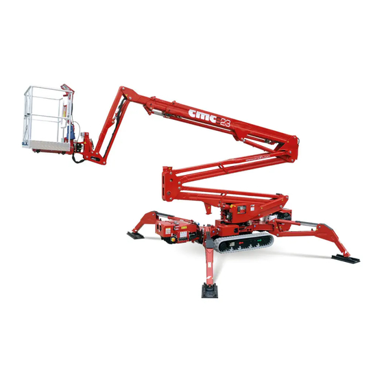
- Page 7 vertical use. It must be travelled only when it is totally folded in the transport position. The machine is called S23 and it is a mobile ele- ➔ vating work platform (MEWP): The use of the machine is allowed only to •...
-
Page 8: Tüv Certification
MEWP in its transport Loading cycle: a cycle starts from the access position, continues performing the work and finishes returning to the access position. MAN.241 Rev.5 ENG - Use and maintenance manual S23 page... -
Page 9: Identification Plate
1.7 Identification plate On the turret there is a tag where all identification data of the machine are engraved: Picture 1: identification plate. MAN.241 Rev.5 ENG - Use and maintenance manual S23 page... -
Page 10: Specifications
1,75 x 5.74 x Tracks (L x w) Max. slope to travel (lon- 0,25 m 0.82 ft 17°-10° / 31%-18% gitudinally/transversally) 0,85/1,25 2.79/4.10 Tracks widening (*optional) 0,60-1,40 0.37-0.88 Travel speed km/h MAN.241 Rev.5 ENG - Use and maintenance manual S23 page... - Page 11 45.88 lb/ft work (narrow area) (2,20 KN/m²) Tightening (Y) Max. pressure in 258 kg/m² torque 52.84 lb/ft work (mixed area) (2,53 KN/m²) Slewing ring bolts M16 cl 10.9 28 daNm MAN.241 Rev.5 ENG - Use and maintenance manual S23 page...
- Page 12 MAN.241 Rev.5 ENG - Use and maintenance manual S23 page...
- Page 13 MAN.241 Rev.5 ENG - Use and maintenance manual S23 page...
- Page 14 2.2 Work diagram Picture 2b: work areas. Picture 2a: work diagram. MAN.241 Rev.5 ENG - Use and maintenance manual S23 page...
-
Page 15: Description Of The Main Components
2.3 Description of the main components Picture 3: main components of the MEWP. MAN.241 Rev.5 ENG - Use and maintenance manual S23 page... - Page 16 The basket 16 (Picture 3) is connected to the second extensible boom through the jib 15 (Picture 3). It is MAN.241 Rev.5 ENG - Use and maintenance manual S23 page...
- Page 17 1.1 m from the floor, an intermediate guard-rail and a foot guard band along all the sides of the platform. The floor is in anti-skid and self-draining aluminium. MAN.241 Rev.5 ENG - Use and maintenance manual S23 page...
- Page 18 • the fuse box. It consists of an electrical panel (Picture 4a) in which there are: In addition, on the left side of this case (Picture 4a), you can find: MAN.241 Rev.5 ENG - Use and maintenance manual S23 page...
- Page 19 7: if lighted on, it allows the maneuvers of the aerial part only with stabilization correctly performed. • the stabilization consent light 8: if lighted on, it allows the movement of the outriggers only MAN.241 Rev.5 ENG - Use and maintenance manual S23 page...
- Page 20 SK key is in position I; • the fuse box; • the hour counter HC. Picture 4c: electric station in case of gasoline engine. MAN.241 Rev.5 ENG - Use and maintenance manual S23 page...
- Page 21 MEWP must never works without the support. machine engine while keeping the key on the symbol (Figura 4e) MAN.241 Rev.5 ENG - Use and maintenance manual S23 page...
- Page 22 SK key all the way to the left on posi- • tion 0; from the radio/wired control, start the engine by pushing the lever in Picture 5 downwards; MAN.241 Rev.5 ENG - Use and maintenance manual S23 page...
- Page 23 110 V and 230 V. The desired one can be set thanks to a special electric selector (Pic- ture 7a - *optional) fixed to the frame. MAN.241 Rev.5 ENG - Use and maintenance manual S23 page...
- Page 24 48 V electric engine powered by 160 Ah lithium 10%), all work maneuvers will be inter- batteries. rupted, and it will only be possible to close the machine again. MAN.241 Rev.5 ENG - Use and maintenance manual S23 page...
- Page 25 The system will select as actual control station the first one that will be used by the operator. Once the MAN.241 Rev.5 ENG - Use and maintenance manual S23 page...
- Page 26 MAN.241 Rev.5 ENG - Use and maintenance manual S23 page...
- Page 27 Picture 8b: radio control station. MAN.241 Rev.5 ENG - Use and maintenance manual S23 page...
- Page 28 (yellow); mum slope reaching, keeping the lever up- ward; • • joystick J3 for boom lifting/lowering lever 8 for endothermic or electric* en- (yellow); gine power on/off; MAN.241 Rev.5 ENG - Use and maintenance manual S23 page...
- Page 29 LED – RIGHT FRONT STABILIZER TO ket levelling operation when the machine THE GROUND is developed. LED – DANGER/GENERIC FAULT on the right side: WARNING LIGHT – ANTI-CRASH SYSTEM • electropump activation button. MAN.241 Rev.5 ENG - Use and maintenance manual S23 page...
- Page 30 (*optional) non-working hours. 25. LED – BOOMS CLOSED 26. LED – TURRET CENTRED 27. LED – BOOMS WITHDRAWN MAN.241 Rev.5 ENG - Use and maintenance manual S23 page...
- Page 31 (Picture 11). Picture 11: frame and basket connector for wired remote control. MAN.241 Rev.5 ENG - Use and maintenance manual S23 page...
- Page 32 On the right side of electronic box, below the basket con- trol station, there can be also a 12 V socket* and a 200 bar air/water hose*. MAN.241 Rev.5 ENG - Use and maintenance manual S23 page...
- Page 33 Picture 13: outriggers control station. • lever 1 for left rear stabilizer; • lever 2 for right rear stabilizer; • lever 3 for left front stabilizer; • lever 4 for right front stabilizer; MAN.241 Rev.5 ENG - Use and maintenance manual S23 page...
- Page 34 Picture 14: display. Communicate the failure code shown on the display, when you require technical assis- tance to C.M.C. Service or authorized work- shops. MAN.241 Rev.5 ENG - Use and maintenance manual S23 page...
- Page 35 MEWP aerial part by the operator on the ground. MAN.241 Rev.5 ENG - Use and maintenance manual S23 page...
-
Page 36: Use Procedures
Technical Assis- hats, safety glasses and shoes, gloves and earmuffs tance Service before use. MAN.241 Rev.5 ENG - Use and maintenance manual S23 page... - Page 37 We recommend the use of an anemome- ter, to determine direction and speed of wind. Any addition that increases the wind load on the MEWP, such as warning signs, is prohibited. MAN.241 Rev.5 ENG - Use and maintenance manual S23 page...
-
Page 38: Transport, Storage And Pack- Aging
14° (25%). If you choose this option, please proceed with the following procedure, care- fully reading the danger notes suggested. MAN.241 Rev.5 ENG - Use and maintenance manual S23 page... - Page 39 The tracks should be extended to maximum not higher than 14° (25%) and that they are width for improved stability and increased perfectly clean from grease, mud, snow or ice. ground clearance when loading and unload- MAN.241 Rev.5 ENG - Use and maintenance manual S23 page...
- Page 40 In order to avoid the overturning of the MEWP, use the roll-over control lever 9 (Pic- ture 8), present on radio control station: it MAN.241 Rev.5 ENG - Use and maintenance manual S23 page...
- Page 41 9 (Picture 8) 3. make sure the booms are returned and on to balance the weight of machine. their support; 4. turn on the machine (par. 3.1); MAN.241 Rev.5 ENG - Use and maintenance manual S23 page...
- Page 42 Picture 17: travel commands on J6 (Picture 8b). radio control station. WARNING! The S23 machine can travel on a maximum inclination of 17° (31%), us- ing only the radio control. MAN.241 Rev.5 ENG - Use and maintenance manual S23 page...
- Page 43 • automatic stabilization, contact point of every stabilizer plate with • automatic speed control, the ground; • automatic closing of the aerial part. MAN.241 Rev.5 ENG - Use and maintenance manual S23 page...
- Page 44 (4 feet closed); b. wide (4 feet opened), c. mixed (2 feet closed, and 2 feet opened). A double electronic locking system uniquely ensures the chosen working configuration. Picture 18: outrigger pins. MAN.241 Rev.5 ENG - Use and maintenance manual S23 page...
- Page 45 MAN.241 Rev.5 ENG - Use and maintenance manual S23 page...
- Page 46 7 (Picture 4) is on. During stabilization phase, pressing the parking but- Picture 19: basket assembly. ton P (Picture 8) on the radio control, together the MAN.241 Rev.5 ENG - Use and maintenance manual S23 page...
- Page 47 MEWP by using ad- figuration. ditional equipment. It is strictly forbidden to level the basket It is forbidden to use the MEWP as a lifting with the machine developed. device. MAN.241 Rev.5 ENG - Use and maintenance manual S23 page...
- Page 48 ➔ The operator must remove the overload from the basket to continue the work with the MEWP. MAN.241 Rev.5 ENG - Use and maintenance manual S23 page...
- Page 49 P simultaneously to raised, the stabilizers with their curved structure can the desired operation. The sudden or intentional release MAN.241 Rev.5 ENG - Use and maintenance manual S23 page...
- Page 50 Keeping the parking button P (Picture 8) pressed, to- ies. gether the J5 joystick which control the turret rotation, you can activate the turret self-centering up to the po- sition 0°. MAN.241 Rev.5 ENG - Use and maintenance manual S23 page...
-
Page 51: "Home" Function
THE BUTTON AND PROCEED WITH THE the machine. MANUAL MANOEUVRES. Then operate according to the following procedure: switch off the electric engine; MAN.241 Rev.5 ENG - Use and maintenance manual S23 page... - Page 52 In case of emergency, the controls of the MEWP The charge times are: aerial part can be performed by the operator on the ground. BATTERY CHARGE TIME 0% - 80% 80%-100% Emergency buttons 4.6.1 MAN.241 Rev.5 ENG - Use and maintenance manual S23 page...
-
Page 53: Emergency Bypass
MEWP. original position (due to blackout, fainting or other), it will be possible to disable that safety function through MAN.241 Rev.5 ENG - Use and maintenance manual S23 page... - Page 54 Picture 20, at the right safe. side of the emergency control station. 1. Turn the manual pump tap (Picture 21) on the position represented by the platform symbol (fully to the bottom). MAN.241 Rev.5 ENG - Use and maintenance manual S23 page...
- Page 55 PV (Picture 2. Unseal and fully screw the black knob of the 23a) of the emergency workbench. tap LFT (Picture 22) at the left of the filters bench. MAN.241 Rev.5 ENG - Use and maintenance manual S23 page...
- Page 56 3; iv. pantograph lowering 4; Picture 23b: emergency workbench v. basket levelling 1; in case of moment limiter device (*optional). vi. turret rotation, keeping pressed 6 to- gether 1. MAN.241 Rev.5 ENG - Use and maintenance manual S23 page...
- Page 57 At the end of aerial part recovery, it is pos- sible to get the operators off the basket. MAN.241 Rev.5 ENG - Use and maintenance manual S23 page...
- Page 58 Picture 25: manual pump tap to be turned to the top. Unseal and fully screw the black knob of the tap RFT (Picture 26) located at the right of the filters bench. MAN.241 Rev.5 ENG - Use and maintenance manual S23 page...
- Page 59 Execute the tracks re-entry (*optional) mov- riggers control station. ing upward the lever 5 on outriggers control station (Picture 13). It is strictly forbidden to use the MEWP with solenoid valves tampered or without seals. MAN.241 Rev.5 ENG - Use and maintenance manual S23 page...
- Page 60 ANY DIFFERENT USE IS ABSOLUTELY NOT RECOMMENDED. IN FACT, THE ELECTRIC PUMP, ABSORBING POWER DIRECTLY FROM THE BATTERY, PRODUCE UNEXPECTED DISCHARGE OF IT. MAN.241 Rev.5 ENG - Use and maintenance manual S23 page...
- Page 61 (Picture 29) under the red sealed cap on the left side of switching on/off box. In case of emergency, switch on the elec- tropump, repeat the emergency maneu- vers described above, after turning the MAN.241 Rev.5 ENG - Use and maintenance manual S23 page...
- Page 62 Do not use the MEWP under drug or alcohol effect; Picture 30: electropump tap. Do not use the MEWP under stress condi- tions; MAN.241 Rev.5 ENG - Use and maintenance manual S23 page...
- Page 63 4.7.2 ities coming from an incorrect functioning of the safety devices. ➔ Carefully and chronologically follow the instruc- tions given in this manual; Do not remove or modify safety devices; MAN.241 Rev.5 ENG - Use and maintenance manual S23 page...
- Page 64 Check that nobody is within the MEWP action MEWP range. ➔ Stabilize the truck through the outriggers. It is forbidden to operate in situations which are dangerous for the safety of people; MAN.241 Rev.5 ENG - Use and maintenance manual S23 page...
- Page 65 Do not overload the MEWP; the work (which shall be carried out without MAN.241 Rev.5 ENG - Use and maintenance manual S23 page...
- Page 66 It is forbidden to use the MEWP for recrea- crushing, shearing hazard; keep manuals tional purposes; away from any hole or slit; MAN.241 Rev.5 ENG - Use and maintenance manual S23 page...
- Page 67 It is forbidden to make the platform swing; ➔ Check the MEWP stability during all the opera- It is forbidden to exceed the max number of tions phases; basket operators allowed; MAN.241 Rev.5 ENG - Use and maintenance manual S23 page...
-
Page 68: Safety Devices
Do not intervene on your own safety de- vices. In case of tampering, the manufac- turer declines all responsibility about any accidents attributable to these interven- tions. MAN.241 Rev.5 ENG - Use and maintenance manual S23 page... - Page 69 Interlock stabilizers-boom manoeuvre: • Limit switch stabilizers opening. - block of the manoeuvres of the MEWP • Limit switch boom lifting-lowering in parking aerial part when this is not stabilized; position. MAN.241 Rev.5 ENG - Use and maintenance manual S23 page...
-
Page 70: Residual Risks
After refuelling, make sure the cap is closed batteries and remove the ignition key. During securely and appropriately. washing, the machine must be turned off and disconnected from the power supply. MAN.241 Rev.5 ENG - Use and maintenance manual S23 page... -
Page 71: Noise And Vibrations
Conformity of the machine. During the phases of tance. use of the machine for aerial operations, this value is MAN.241 Rev.5 ENG - Use and maintenance manual S23 page... - Page 72 Before using the MEWP, it is compulsory to check the presence and the perfect readabil- ity of these decals. In case of their absence or decay, contact the Service. Picture 31: identification plate (facsimile). MAN.241 Rev.5 ENG - Use and maintenance manual S23 page...
- Page 73 Picture 32: MEWP model mark. Picture 33: maximum load in basket. Picture 34: work diagram. MAN.241 Rev.5 ENG - Use and maintenance manual S23 page...
- Page 74 Picture 35b: switching on/off box in case of Picture 35a: switching on/off box in case of die- Full lithium version sel engine. Picture 36: AUTEC radio control station. MAN.241 Rev.5 ENG - Use and maintenance manual S23 page...
- Page 75 Picture 41: safety belt attachment point. Picture 38: AUTEC electronic panel of radio/wired control station. Picture 42: indication of air/water supplies. Picture 43: indication of 12 V socket. Picture 39: display box. MAN.241 Rev.5 ENG - Use and maintenance manual S23 page...
- Page 76 Picture 46: use and maintenance manual box. Picture 44: travel directions on tracks. Picture 47: indication of maximum frame inclination. Picture 45: maximum slopes for travel. Picture 75: Warning for leveling before opera- tion. MAN.241 Rev.5 ENG - Use and maintenance manual S23 page...
- Page 77 Picture 48: outriggers control station. Picture 53: indication for fuel refill. Picture 56: indication for grease application. Picture 57: indication for engine oil checking/refill and type. Picture 49: maximum load on stabilizers. MAN.241 Rev.5 ENG - Use and maintenance manual S23 page...
- Page 78 Picture 59: auxiliary electric engines (*optional). Picture 63: indication of fork points. Picture 60: indication for engine battery disconnection. Picture 68: indication of engine oil level. Picture 61: indication of platform fuse. MAN.241 Rev.5 ENG - Use and maintenance manual S23 page...
- Page 79 Picture 66: cursor for basket centring. Picture 71: aerial part/stabilizers exchange tap in case of manual pump. Picture 67: dead man button for stabilization. Picture 68: MEWP/outriggers workbench. MAN.241 Rev.5 ENG - Use and maintenance manual S23 page...
- Page 80 Picture 74: warning of burn risk. Picture 72: general obligations and prohibitions. Picture 75: earthing. Picture 76: electric danger. Picture 73: warning for tracks lifting during stabilization. Picture 77: crushing and cutting hazard. MAN.241 Rev.5 ENG - Use and maintenance manual S23 page...
- Page 81 Picture 81: machine sound power. Picture 82: prohibition to wet the machine. Picture 84: MEWP use guidelines. Picture 83: warning to obligate to the consulta- tion of use and maintenance manual. MAN.241 Rev.5 ENG - Use and maintenance manual S23 page...
- Page 82 Picture 85: compliance with ANSI and CAN/CSA rules. Picture 86: inspection tag. MAN.241 Rev.5 ENG - Use and maintenance manual S23 page...
-
Page 83: Electrical System
MEWP have been calibrated: a correct calibration of these parts (which is possi- ble only in CMC or in authorized Services) is important to assure the safety of the ma- chine. Picture 87: fuse box. MAN.241 Rev.5 ENG - Use and maintenance manual S23 page... - Page 84 TURRET AND BASKET Fuse 6 POWER SUPPLY CHASSIS DEVICE POWER Fuse 7 SUPPLY Fuse 8 EMERGENCY LINE 15/54 Fuse 9 TURRET POWER SUPPLY Fuse 10 STOP ENGINE Table 4: fuse functions. MAN.241 Rev.5 ENG - Use and maintenance manual S23 page...
-
Page 85: Hydraulic System
200 (2901) bar (psi) parts (only in CMC or in authorized Ser- Pressure relief valve of 225 (3263) bar (psi) vices) is necessary to ensure the safety of tracks the machine. MAN.241 Rev.5 ENG - Use and maintenance manual S23 page... -
Page 86: Maintenance
The operations indicated with o installed and used in accordance with CMC shall be performed only by C.M.C. srl or in au- the use instructions; thorized repair shops. o subject to proper maintenance in order... -
Page 87: Daily Maintenance
Check the level of the Top up USER turret; fuel in the tank. o extend and withdraw Check the level of the Top up USER the telescopic boom. coolant liquid. MAN.241 Rev.5 ENG - Use and maintenance manual S23 page... - Page 88 Contact the of the outriggers. drawal; Service. o operate the levers for OUTRIGGERS SHALL NOT MOVE. the lifting and lowering of the telescopic boom. BOOMS SHALL MOVE. MAN.241 Rev.5 ENG - Use and maintenance manual S23 page...
- Page 89 MEWP. basket control station boom until the max out- Contact the to lift the aerial part. Service. reach indicated in work AERIAL PART diagram. SHALL NOT MOVE. MAN.241 Rev.5 ENG - Use and maintenance manual S23 page...
- Page 90 Check that the electri- C.M.C. strictly forbidden Reset connec- USER/ the emergency but- cal contacts are not to use the MEWP. tions. C.M.C. tons work perfectly. slacken. Contact the Ser- vice. MAN.241 Rev.5 ENG - Use and maintenance manual S23 page...
- Page 91 Replace- USER/ lift the pantograph (Picture 88); thermic engine and ment. C.M.C. rotate the turret of 90° counterclockwise auxiliary motor* air (Picture 88); filters. turn off MEWP’s engine; MAN.241 Rev.5 ENG - Use and maintenance manual S23 page...
- Page 92 90); graph lifted and turret rotated of 90° counter- inject the grease with the apposite syringe; clockwise) for grease injection. put red pressure caps (Picture 89 – Picture 90);. MAN.241 Rev.5 ENG - Use and maintenance manual S23 page...
- Page 93 8.5 Maintenance after the first 400 hours Operations Picture 90: red pressure caps on side of rotation Replacement of the hydraulic fil- USER / group (bearing). ters. Registration of the movement of the booms. MAN.241 Rev.5 ENG - Use and maintenance manual S23 page...
-
Page 94: Six-Monthly Maintenance
2. Suck the oil from the tank; 3. Remove the hydraulic filter; 4. Replace the filter; MAN.241 Rev.5 ENG - Use and maintenance manual S23 page... -
Page 95: Safety Rules During Mainte- Nance
MEWP truck: mark the area assigned for the mainte- engine stalled and no component in movement. nance operations by suited enclosure or by a MAN.241 Rev.5 ENG - Use and maintenance manual S23 page... - Page 96 H) x 1470 tion, 2 vertical cylinders. Fuel consumption at 3600 rpm Unit of Data Value Fuel tank capacity measure Ø 72 x 73.6 Bore x Stroke MAN.241 Rev.5 ENG - Use and maintenance manual S23 page...
- Page 97 Cells Configuration 15S1P *When charge is operated at less than 0°C the Rated Voltage charge current is electronically limited at 10 A. Maximum Voltage 54.8 Fully Charge Battery charger specifics MAN.241 Rev.5 ENG - Use and maintenance manual S23 page...
- Page 98 Viscosity Index ASTM Kinematic Viscosity, 100°C, D2270 ASTM D445 12,9 mm2/s Pour point °C ASTM D97 Viscosity Index ASTM D2270 Flash point COC, ASTM D92 Pour point °C ASTM D97 °C MAN.241 Rev.5 ENG - Use and maintenance manual S23 page...
- Page 99 Before oil replacement, place an oil drip tray ▪ Oils and lubricants: hydraulic oil, reducers lubri- in order to avoid the leakage of oil in the en- cants, lubricating greases. vironment. Do not disperse the exhausted MAN.241 Rev.5 ENG - Use and maintenance manual S23 page...
- Page 100 MODEL AND SERIAL NUMBER OF THE MEWP. Picture 91: remote connection system. Any operation requiring interventions on the components of the machine shall be carried out by authorized and trained staff. MAN.241 Rev.5 ENG - Use and maintenance manual S23 page...
- Page 101 • the led on the remote connection box makes two red flashes, • after 30 seconds, the led becomes fixed and green, to show that the operating system is working, MAN.241 Rev.5 ENG - Use and maintenance manual S23 page...
-
Page 102: Troubleshooting
2. Replace the stabilizers limit 3. Replace the exchange valve. switches. 4. Turn the emergency button and re If the problem persists, contact the Service. set the MEWP. _________________________________________ MAN.241 Rev.5 ENG - Use and maintenance manual S23 page... - Page 103 START ENDOTHERMIC ENGINE. Causes: 1. Emergency activated. 2. Battery discharged. 3. Out of fuel. 4. Hydraulic oil level too low. Remedies: 1. Disable the emergency button. 2. Replace the battery. MAN.241 Rev.5 ENG - Use and maintenance manual S23 page...
- Page 104 The tampering or replacement of compo- nents by non-authorized staff is strictly forbidden. ➔ It is mandatory to restore the sealings after use of these items. MAN.241 Rev.5 ENG - Use and maintenance manual S23 page...
- Page 105 You shall not repeat 200 (NL) hori- tests with the same loads. 11,40 at 40° lateral zontal 100 (TL) NOTES. NL: nominal load. TL: test load. MAN.241 Rev.5 ENG - Use and maintenance manual S23 page...
-
Page 106: Functional Tests
Aerial part operations block when the MEWP is not stabilized • Block of the return/extension of out- riggers when the MEWP aerial part is not set in the rest position. MAN.241 Rev.5 ENG - Use and maintenance manual S23 page... -
Page 107: Control Register
➢ Replacement of safety devices (par. 13.7) ➢ Failure of a certain entity and their repairs (par. 13.8) ➢ Periodic inspections and maintenance log (par. 13.9) ➢ Notes (par. 13.10) MAN.241 Rev.5 ENG - Use and maintenance manual S23 page... - Page 108 The seller The buyer The seller The buyer MAN.241 Rev.5 ENG - Use and maintenance manual S23 page...
- Page 109 The seller The buyer The seller The buyer MAN.241 Rev.5 ENG - Use and maintenance manual S23 page...
- Page 110 Place……………… Place……………… Date……………… Date……………… Stamp and signature of the responsible Stamp and signature of the responsible for the firm in charge The user for the firm in charge The user MAN.241 Rev.5 ENG - Use and maintenance manual S23 page...
- Page 111 Place……………… Place……………… Date……………… Date……………… Stamp and signature of the responsible Stamp and signature of the responsible for the firm in charge The user for the firm in charge The user MAN.241 Rev.5 ENG - Use and maintenance manual S23 page...
- Page 112 Place……………… Place……………… Date……………… Date……………… Stamp and signature of the responsible Stamp and signature of the responsible for the firm in charge The user for the firm in charge The user MAN.241 Rev.5 ENG - Use and maintenance manual S23 page...
- Page 113 Place……………… Place……………… Date……………… Date……………… Stamp and signature of the responsible Stamp and signature of the responsible for the firm in charge The user for the firm in charge The user MAN.241 Rev.5 ENG - Use and maintenance manual S23 page...
- Page 114 Place……………… Place……………… Date……………… Date……………… Stamp and signature of the responsible Stamp and signature of the responsible for the firm in charge The user for the firm in charge The user MAN.241 Rev.5 ENG - Use and maintenance manual S23 page...
- Page 115 Place……………… Place……………… Date……………… Date……………… Stamp and signature of the responsible Stamp and signature of the responsible for the firm in charge The user for the firm in charge The user MAN.241 Rev.5 ENG - Use and maintenance manual S23 page...
-
Page 116: Replacement Of Electrical Compo- Nents
Place……………… Place……………… Date……………… Date……………… Stamp and signature of the responsible Stamp and signature of the responsible for the firm in charge The user for the firm in charge The user MAN.241 Rev.5 ENG - Use and maintenance manual S23 page... - Page 117 Place……………… Place……………… Date……………… Date……………… Stamp and signature of the responsible Stamp and signature of the responsible for the firm in charge The user for the firm in charge The user MAN.241 Rev.5 ENG - Use and maintenance manual S23 page...
- Page 118 Place……………… Place……………… Date……………… Date……………… Stamp and signature of the responsible Stamp and signature of the responsible for the firm in charge The user for the firm in charge The user MAN.241 Rev.5 ENG - Use and maintenance manual S23 page...
- Page 119 Place……………… Place……………… Date……………… Date……………… Stamp and signature of the responsible Stamp and signature of the responsible for the firm in charge The user for the firm in charge The user MAN.241 Rev.5 ENG - Use and maintenance manual S23 page...
- Page 120 Place………. Date…………… Place………. Date…………… Stamp and signature of the responsible Stamp and signature of the responsible for the firm in charge The user for the firm in charge The user MAN.241 Rev.5 ENG - Use and maintenance manual S23 page...
- Page 121 Place………. Date…………… Place………. Date…………… Stamp and signature of the responsible Stamp and signature of the responsible for the firm in charge The user for the firm in charge The user MAN.241 Rev.5 ENG - Use and maintenance manual S23 page...
- Page 122 SIGNATURE nance journal THE INTERVENTION ➔ The user has the obligation to respect the maintenance control program described in this manual and to register the inspections in a proper journal. MAN.241 Rev.5 ENG - Use and maintenance manual S23 page...
- Page 123 DESCRIPTION OF DESCRIPTION OF DATE SIGNATURE DATE SIGNATURE THE INTERVENTION THE INTERVENTION MAN.241 Rev.5 ENG - Use and maintenance manual S23 page...
- Page 124 DESCRIPTION OF DESCRIPTION OF DATE SIGNATURE DATE SIGNATURE THE INTERVENTION THE INTERVENTION MAN.241 Rev.5 ENG - Use and maintenance manual S23 page...
- Page 125 13.10 Notes …………………………………………………… …………………………………………………… …………………………………………………… …………………………………………………… …………………………………………………… …………………………………………………… …………………………………………………… …………………………………………………… …………………………………………………… …………………………………………………… …………………………………………………… …………………………………………………… …………………………………………………… …………………………………………………… …………………………………………………… …………………………………………………… …………………………………………………… …………………………………………………… …………………………………………………… …………………………………………………… …………………………………………………… …………………………………………………… …………………………………………………… …………………………………………………… MAN.241 Rev.5 ENG - Use and maintenance manual S23 page...
- Page 126 Description of the main components hours) 90 Quarterly maintenance (or every 300 hours) 92 3Command stations 17 Maintenance after the first 400 hours Machine switching on/off station 17 Platform control stations 24 MAN.241 Rev.5 ENG - Use and maintenance manual S23 page...
- Page 127 12Functional tests 105 13Control register 106 Delivery of the MEWP to the first 13.1 owner 106 Further transfers of ownership 107 13.2 Replacement of mechanisms 109 13.3 Replacement of structural elements 13.4 MAN.241 Rev.5 ENG - Use and maintenance manual S23 page...
- Page 128 Via Bitritto, 119 - 70124 BARI - ITALY Tel. +39 080 532 66 06 - Fax +39 080 536 85 41 www.cmclift.com - info@cmclift.com Follow us on...
Need help?
Do you have a question about the S23 and is the answer not in the manual?
Questions and answers