Advertisement
Quick Links
JUMPER SETTING & CONNECTORS
DB 9M:
Serial 9 Pin D-SUB connector
Pin
Signal
Pin
Signal
1
CDC
4
DTR
2
RXD
5
GROUND
3
TXD
6
DSR
HARDWARE INSTALLATION
If you are ready with the jumper settings, please proceed with the following installation instructions.
Because there are large differences between PC's, we can give you only a general installation
guide. Please refer to your computer's reference manual whenever in doubt.
1.
Turn off the power to your computer and any other connected peripherals.
2.
Remove the mounting screws located at the rear and/ or sides panels of your Computer and
gently slide the cover off.
3.
Locate an available expansion slot and remove its covers from the rear panel of your comput-
er. Make sure it is the right expansion slot for the card (see card description)
4.
Align the card with the expansion slot, and then gently but firmly, insert the card. Make sure
the card is seated and oriented correctly. Never insert the card by force!
5.
Then connect the card with a screw to the rear panel of the computer case.
6.
Gently replace your computer's cover and the mounting screws.
DRIVER INSTALLATION
Windows
After completing the hardware installation, the operating system will automatically the card and
install this! If the driver should not be installed automatically, insert the driver CD into you CD-
ROM drive (eg drive D:) and then open the folder „IO/MOSCHIP/MCS99xx". Please select the
folder with your operating system and install the driver (see Picture). Follow the hardware
assistant and finish the installation. Important! Restart your PC in any case after installing the
drivers.
5
DRIVER INSTALLATION
CHECK INSTALLED DRIVER
Open the >Device manager<. Now you should see at „Ports (COM & LPT)" and at
„Multifunction Adapter" the following new entry's:
Pin
Signal
7
RTS
8
CTS
9
RI
If you see this or a similar information the device is installed correctly.
CHANGE PORT NUMBER
If you like to change the port number for example COM3 to COM5, open the „Device Manager"
click at „COM3", „Settings" and then „Advance". There you can change between COM3 till
COM256.
Windows Server 20xx
After completing the hardware installation, the operating system will automatically the card and
install this! If the driver should not be installed automatically, insert the driver CD into you CD-
ROM drive (eg drive D:) and then open the folder „IO/MOSCHIP/MCS99xx". Please select the
folder with your operating system and install the driver (see Picture). Follow the hardware
assistant and finish the installation. Important! Restart your PC in any case after installing the
drivers.
Use the following driver for the following Windows Server Version.
Windows Server 2003
Windows Server 2008
Windows Server 2008R2 =
Windows Server 2012
Windows Server 2012R2 =
CHECK INSTALLED DRIVER
Open the >Device manager<. Now you should see at „Ports (COM & LPT)" and at
„Multifunction Adapter" the following new entry's:
CHANGE PORT NUMBER
If you like to change the port number for example COM3 to COM5, open the „Device Manager"
click at „COM3", „Settings" and then „Advance". There you can change between COM3 till
COM256.
MS-DOS
Please read the manual on the driver CD. You will find the manual in the following folder
„IO/MOSCHIP/MCS99xx/DOS".
LINUX
The required Linux driver are located in the following directory
=
XP Driver
=
VISTA Driver
Windows 7 Driver
=
Windows 8.x Driver
Windows 10 Driver
„IO/MOSCHIP/MCS99xx/Linux".
6
Manuale d'uso
STRUTTURA
JP2: Alimentazione
JP1:
su 9 Pin
ON/OFF
(alimentazione o bus PCI-Express)
S1-S4: Connettore da 44 pin
a 4 x 9 pin
P t
i l
DESCRIZIONE & DATI TECNICI
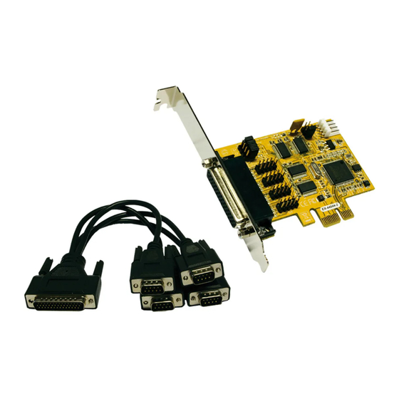
La EX-44044-2 è una scheda seriale RS-232 PCI-Express con 4 porte seriali FIFO 16C550, per il
collegamento di dispositivi periferici seriali RS-232 ad alta velocità (ad esempio terminale,
modem, plotter, ecc.). Il bus seriale PCI-Express supporta in modo ottimale le prestazioni del
veloce chipset 16C550 con cache FIFO da 256 byte. La scheda garantisce una trasmissione dati
sicura e prestazioni eccellenti fino a 115,2KBaud/s! Supporta tutti gli slot PCI Express da x1 a
x16. Non è possibile impostare manualmente gli indirizzi I/O e gli interrupt perché le impostazioni
della scheda vengono effettuate automaticamente dal sistema (BIOS) e dal sistema operativo.
Compatibilità:
PCI-Express x1 fino a x16
Sistema Operativo:
Windows DOS/ 2000/ XP/ Vista/ 7/ 8.x/ 10/ Server 20xx/ Mac/ Linux
Connettore:
4x 9 Pin Seriale D-Sub Maschio
Confezione :
EX-44044-2, Driver CD, Manuale, Staffe a Basso Profilo,
cavo Octopus
CE / FCC / RoHS / WEEE
Certificati:
DE97424562 / WHQL
SETTAGGIO JUMPER & ATTACCHI
If you see this or a similar information the device is instal
JP2:
DIS
= Il segnale standard RI (Ring Indicator) si trova sul pin 9
(impostazione di fabbrica)
PWR
= Sul pin 9 è ora possibile impostare una tensione di DC5V o
DC12V
Si regola la tensione utilizzando JP1. Tuttavia, questo non dovrebbe
essere modificato per le applicazioni standard.
JP1:
Se è stato impostato il ponticello JP2 per PWR, è possibile utilizzare il
AUX5V
ponticello JP1 per impostare il valore della tensione. Esistono 3 diverse fonti
AUX12V
di tensione. (Solo in combinazione con JP2 su PWR!!!)
PCI12V
AUX5V = 5 volt dall'alimentatore del PC
AUX12V = 12 volt dall'alimentatore del PC
PCI12V = 12 volt dalla scheda madre (impostazione di fabbrica)
J3:
1 +5V
Per l'impostazione AUX (JP1), J3 deve essere collegato all'alimentazione
2 GND
del PC! In caso contrario la scheda non verrà alimentata.
3 GND
4 +12V
1
EX-44044-2
Ponticello per la fonte di alimentazione
J3:
Collegamento per l'elettricità
dall'alimentatore del PC
J1-J4: Porta seriale interna
Advertisement

Related Manuals for Exsys EX-44044-2


Summary of Contents for Exsys EX-44044-2
- Page 1 Use the following driver for the following Windows Server Version. Windows Server 2003 XP Driver La EX-44044-2 è una scheda seriale RS-232 PCI-Express con 4 porte seriali FIFO 16C550, per il Windows Server 2008 VISTA Driver collegamento di dispositivi periferici seriali RS-232 ad alta velocità (ad esempio terminale,...
- Page 2 6. Ora puoi chiudere nuovamente la custodia del computer con le viti. Windows Server 2008 VISTA Driver The EX-44044-2 is a plug & play high-speed serial RS-232 expansion card for the PCI-Express Windows Server 2008R2 = Windows 7 Driver Bus. It provides four 9 pin high speed RS-232 serial ports. It uses data transfer rates up to Windows Server 2012 Windows 8.x Driver...
Need help?
Do you have a question about the EX-44044-2 and is the answer not in the manual?
Questions and answers