Advertisement
Quick Links
EX-44088
JUMPER SETTING & CONNECTORS
JP1:
DIS
= The function PME is disable (Factory Setting)
DIS | ENA
ENA
= The function PME is enable. Now the card can be activate
the computer through the serial ports.
J5:
1 +5V
For aux power (JP5), J5 must be connected to pc power supply!
2 GND
3 GND
If not, the card wont work.
4 +12V
DB 9M:
Serial 9 Pin D-SUB male connector
Pin
Signal
Pin
1
CDC
4
2
RXD
5
GROUND
3
TXD
6
DB62F:
Serial 62 Pin female connector
Pin
Signal
Pin
1
TXD 1
22
2
DTR 1
23
3
RXD 2
24
4
DSR 2
25
5
DCD 2
26
6
TXD 3
27
7
DTR 3
28
8
RXD 4
29
9
DSR 4
30
10
DCD 4
31
11
RXD 5
32
12
DSR 5
33
13
DCD 5
34
14
TXD 6
35
15
DTR 6
36
16
RXD 7
37
17
DSR 7
38
18
DCD 7
39
19
RXD 8
40
20
DSR 8
41
21
DCD 8
42
5
English
EX-44088
HARDWARE INSTALLATION
If you are ready with the jumper settings, please proceed with the following installation instruc-
tions. Because there are large differences between PC's, we can give you only a general installa-
tion guide for the EX-44088. Please refer to your computer's reference manual whenever in
doubt.
1. Turn off the power to your computer and any other connected peripherals.
2. Remove the mounting screws located at the rear and/or sides panels of your Computer
and gently slide the cover off.
3. Locate an available expansion slot and remove its covers from the rear panel of your
computer. Make sure it is the right expansion slot for the card (see card description)
4. Align the card with the PCI-Express slot and then gently but firmly, insert the card. Make
sure the card is seated and oriented correctly. Never insert the card by force!
5. Then connect the card with a screw to the rear panel of the computer case.
6. Gently replace your computer's cover and the mounting screws.
Signal
Pin
Signal
DTR
7
RTS
DRIVER INSTALLATION
8
CTS
DSR
9
RI
Windows 9x/ 2000/ XP/ Vista/ 7/ 8/ Server 20xx
After starting Windows it recognizes a new "PCI Controller" and opens the hardware assis-
tant. Please choose manual installation and put the driver CD into your CD-Rom drive. Now
enter the Path "D:\IO\SYSTEMBASE\"
"32bit_Win2000,XP,2003,Vista,2008,7,8" or "64bit_WinXP,2003,Vista,2008,7,8" into the
Signal
Pin
Signal
box for the Path/Source and click at >next/continue<. Now Windows will search for the drivers
in the specified directory. Follow the hardware assistant and finish the installation. If Windows
RXD 1
43
CTS 1
recognizes other new devices repeat the above described steps. Attention! Restart Windows
DSR 1
44
RTS 1
in any case after installing the drivers.
DCD 1
45
GND
CHECK THE INSTALLED DRIVER
TXD 2
46
CTS 2
Click at Start<>Run< then enter "compmgmt.msc" and click at >OK<. In the windows that
DTR 2
47
RTS 2
open select >Device Manager<. Under "Ports (COM and LPT)" you should find one or more
new "PCI Ports" as sample (Com3). If you see this or similar entries the card is installed
RXD 3
48
CTS 3
correctly.
DSR 3
49
RTS 3
CHANGE PORT NUMBER
DCD 3
50
GND
If you like to change the port number for example COM3 to COM5, open the >Device Manager<
TXD 4
51
CTS 4
click at >COM3<, >Settings< and then >Advance<. There you can change between COM3 till
DTR 4
52
RTS 4
COM256.
GND
53
CTS 5
TXD 5
54
RTS 5
Windows NT 4.0
DTR 5
55
GND
Start Windows NT and insert the driver CD into your CD-ROM drive (for example D:). Click at
>Start< >Run< and enter „D:\IO\SYSTEMBASE\WinNT\Install.exe" then click >OK<. Win-
RXD 6
56
CTS 6
dows NT will now start the setup program and install the driver. Please Restart Windows NT
DSR 6
57
RTS 6
after installing the drivers.
DCD 6
58
GND
CHECK THE INSTALLED DRIVER
TXD 7
59
CTS 7
Click
at
>Start<
DTR 7
60
RTS 7
Diagnostics< then click at >Resource< >IRQ<. Here you should find the entry „09
PCI". Then click at >I/O-Port< here you should see the entries „D400-D407 sysbase 0 PCI"
GND
61
CTS 8
„D800-D802
TXD 8
62
RTS 8
addresses can change depends which system and card is installed. If you see these or similar
entry's the card is installed correctly.
DTR 8
SCO UNIX / LINUX
The drivers are located in the following folder on our driver CD:
"D:\IO\SYSTEMBASE\SCO"
Because each individual distribution and kernel version of Linux is different, sadly we cant
provide a installation instruction. Please refer to the installation manual for standard IO ports
from your Unix/Linux version! In some newer versions of Linux the card will even be installed
automatically after starting Linux.
and then the directory of your
>Programs<
>Administrative
Tools[Common]<
sysbase
0
PCI" and „DC00-DC1F sysbase 0 PCI" for the ports. The I/O
6
English
Bedienungsanleitung
Vers. 1.0 / 11.06.14
STRUTTURA
JP4: Alimentazione sul Pin 9
ENE/DIS
S1-S8: Presa a 62 pin
per cavo Octopus con
connessione seriale 8 x 9
pin
system
CARATTERISTICHE & DATI TECNICI
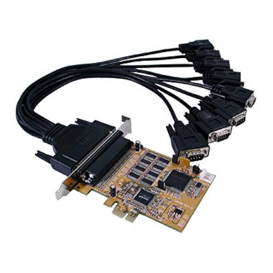
La EX-44088 è una scheda seriale RS-232 PCI-Express con 8 porte seriali FIFO 16C95x, per il
collegamento di dispositivi periferici seriali RS-232 ad alta velocità (ad esempio terminale,
modem, plotter, ecc.). Il bus seriale PCI-Express supporta in modo ottimale le prestazioni del
veloce chipset SystemBase con cache FIFO da 256 byte. L'EX-44088 garantisce una
trasmissione dati sicura e prestazioni eccellenti fino a 921KBaud/s per ogni dispositivo collegato!
Supporta tutti gli slot PCI Express da x1 a x16. Non è possibile impostare manualmente gli
indirizzi I/O e gli interrupt perché le impostazioni della scheda vengono effettuate
automaticamente dal sistema (BIOS) e durante l'installazione del sistema operativo. È possibile
utilizzare i ponticelli per reindirizzare 12 V o 5 V al pin 9 della porta seriale. Assicurati che anche
i dispositivi collegati supportino questo.
PCI-Express x1 fino a x16
Compatibilità:
WIN NT 4.0/ 9x/ 2000/ XP/ Vista/ 7/ 8/ Server 20xx/ Linux
Sistema Operativo:
8x 9 Pin Seriale D-Sub maschio
Connettori:
Confezione:
EX-44088, Driver CD, Manuale, Cavo Octopus
CE / FCC / RoHS / WEEE
Certificato:
SETTAGGIO JUMPER & CONNETTORI
JP4:
>Windows
NT-
DIS
o
0
DIS | PWR
PWR
Regolare la tensione utilizzando JP 5. Tuttavia, questo non dovrebbe
essere modificato per le applicazioni standard.
Se hai impostato il ponticello JP4 su PWR, puoi utilizzare il
JP5:
ponticello JP5 per impostare il valore della tensione. Esistono 4
diverse sorgenti di tensione. (Solo in combinazione con JP4 su
PWR!!!)
X5V
X12V
= 5 volt dall'alimentazione del PC (impostazione di fabbrica)
I12V
X 5V
= 12 volt dall'alimentatore del PC
X 12V
= 12 volt dalla scheda madre
I 12V
JP5: Ponticello per la fonte di alimentazione
(Alimentazione o bus PCI Express)
J5: Connettore per
Alimentazione del PC
SystemBase Chipset
JP1: PME
On/OFF
DE97424562 / WHQL
= Al pin 9 è presente il segnale standard RI (Ring Indicator).
(impostazione di fabbrica)
= Sul pin 9 è ora possibile impostare una tensione di DC5V
o DC12V.
1
Advertisement

Subscribe to Our Youtube Channel
Related Manuals for Exsys EX-44088


Summary of Contents for Exsys EX-44088
- Page 1 TXD 1 RXD 1 CTS 1 recognizes other new devices repeat the above described steps. Attention! Restart Windows La EX-44088 è una scheda seriale RS-232 PCI-Express con 8 porte seriali FIFO 16C95x, per il DTR 1 DSR 1 RTS 1 in any case after installing the drivers.
- Page 2 PC dopo l'installazione. Seriale 62 Pin D-Sub Femmina The EX-44088 is a plug & play high-speed serial RS-232 expansion card for the PCI-Express Bus. The EX-44088 provides eight 9 pin high speed RS-232 serial ports. It uses data transfer Signale Signale...
Need help?
Do you have a question about the EX-44088 and is the answer not in the manual?
Questions and answers