Advertisement
EX
EX-
EX
-
-
6500E
6500E
6500E
HARDWARE INSTALLATION :
If you are ready with the jumper settings for the card, please proceed with the following
installation instructions. Because the designs of computers are different, only general
installation instructions are given. Please refer your computer's reference manual whenever
in doubt.
1. Turn off the power to your computer and any other connected peripherals.
2. Remove the mounting screws located at the rear and/or sides panels of your Com-
puter and gently slide the cover off.
3. If necessary please connect the external power supply to the card like shown at JP1 &
J5 above.
4. Locate an available & correct expansion slot ( see compatibility at technical informa-
tion above) and remove its bracket from the rear panel of your computer.
5. Align the card with the expansion slot, and then gently but firmly, insert the card. Make
sure the card is seated and oriented correctly.
6. Then connect the card with a screw to the rear panel of the computer.
7. Gently replace your computer's cover and the mounting screws.
DRIVER INSTALLATION :
Windows ME
The drivers are already integrated in Windows and the card will be installed automati-
cally.
CHECK INSTALLED DRIVER:
Open the >Device manager< . Now you should see at "IEEE1394 Devices" the following
new entry: <Texas Instruments OHCI conform IEEE1394 Hostcontroller>.
If you see this or a similar information the card is installed correctly.
Windows 2000 XP & Server200x
The drivers are already integrated in Windows and the card will be installed automati-
cally.
CHECK INSTALLED DRIVER:
Open the >Device manager< . Now you should see at "IEEE1394 Devices" the following
new entry: <Texas Instruments OHCI conform IEEE1394 Hostcontroller>.
If you see this or a similar information the card is installed correctly.
Windows Vista & 7
The drivers are already integrated in Windows and the card will be installed automati-
cally.
CHECK INSTALLED DRIVER:
Open the >Device manager< . Now you should see at "IEEE1394 Devices" the following
new entry: <Texas Instruments OHCI conform IEEE1394 Hostcontroller>.
If you see this or a similar information the card is installed correctly.
MAC:
The drivers are already integrated in MAC OS and the card will be installed automati-
cally. Only MacOS 8.6 do need a update before the card can be used. You can
download the update on the MacOS homepage (e.g. FireWire Support 2.8.x)
In doubt please refer to the installation manual from your MAC OS version!
LINUX:
Because each individual distribution and kernel version of Linux is different, sadly we
cant provide a installation instruction here. Please refer to the installation manual for
IEEE1394 ports from your Linux version !
5
English
English
English
EX
EX-
EX
-
-
6500E
6500E
6500E
English
English
English
AUFBAU :
J4: Port 4
Wird mit dem externen Port J3 geteilt
J3: Port 1
Wird mit dem
internen Port J4
geteilt
J2: Port 2
J1: Port 3
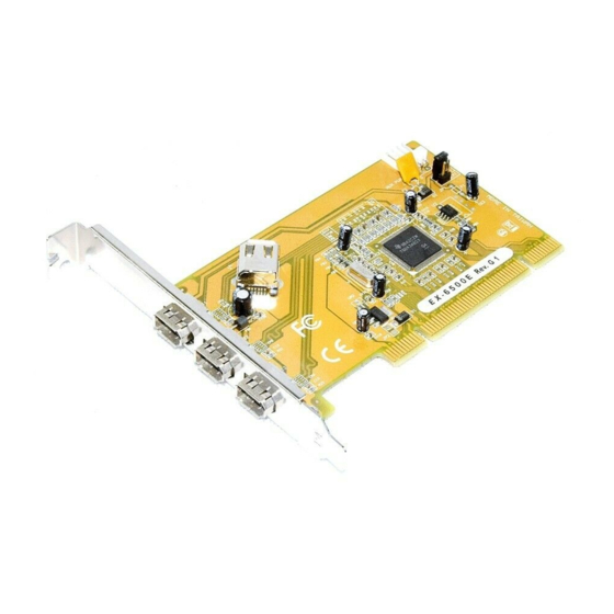
BESCHREIBUNG & TECHNISCHE DATEN :
Die EX-6500E ist eine 32Bit PCI FireWire 1394a Karte mit drei externen und einem
geteiltem internen Ausgang für den Anschluss von Peripheriegeräten mit FireWire
1394a Interface (z.B. Digital Kamera, Digital Aufnahmegerät, Scanner, Soundkarten
usw.). Sie unterstützt den PCI Bus mit 5V und 3,3 Volt. In Verbindung mit dem schnellen
Texas Instruments Chip gewährleistet die EX-6500E eine sichere Datenübertragung
und exzellente Performance von bis zu 400Mbit pro Sekunde! Es ist nicht möglich die I/
O Adressen und Interrupts manuell einzustellen, da die Einstellungen der Karte vom
System (BIOS) und beim Installieren des Betriebssystems automatisch vorgenommen
werden. Sie unterstützt die OHCI Spezifikationen (Open Host Controller Interface).
Kompatibilität:
Betriebssysteme:
Anschlüsse:
Lieferumfang:
Zertifikate:
JUMPER EINSTELLUNG & ANSCHLÜSSE:
JP1:
J5:
J1-J4:
6
Bedienungsanleitung
Bedienungsanleitung
Vers. 3.2 / 12.11.09
PCI & PCI-X 32bit, 5V & 3.3Volt, 33MHz
ME/2000/XP/Vista/7/Server 200x/MAC/Linux (vom OS)
4 x 6 Pin IEEE1394a Buchse, 1 x 4 Pin Stromanschluss
EX-6500E, Anleitung
CE CE CE CE
/ FCC / RoHS / WEEE
DE97424562 / WHQL
INT = Strom vom PCI BUS (Werkseinstellung)
EXT = Strom vom PC-Netzteil des Rechners
INT
(Zur Entlastung des Mainboards und zur stabilen Stromversorgung bei
EXT
Verwendung von Endgeräten mit hohem Stromverbrauch).
Anschluss J5 muss dann mit dem PC-Netzteil verbunden werden!
Wenn JP1 auf EXT gestellt ist muss J5 mit dem Stromanschluss vom
PC Netzteil verbunden werden! Bitte auf die richtige Polarität achten!
Achtung! Stecker nie bei eingeschaltetem PC ein oder ausstecken!
1394 6 Pin Firewire Buchse:
2 4 6
Pin
Signal
1
Power
2
GND
3
TPB-
1 3 5
1
J5
Anschluss für Stecker
vom PC-Netzteil
JP1
Stromquelle wählen
INT oder EXT
TI Chipset
Pin
Signal
4
TPB+
5
TPA-
6
TPA+
Advertisement
Table of Contents

Related Manuals for Exsys EX-6500E


Summary of Contents for Exsys EX-6500E
- Page 1 Open the >Device manager< . Now you should see at “IEEE1394 Devices“ the following new entry: <Texas Instruments OHCI conform IEEE1394 Hostcontroller>. Die EX-6500E ist eine 32Bit PCI FireWire 1394a Karte mit drei externen und einem geteiltem internen Ausgang für den Anschluss von Peripheriegeräten mit FireWire If you see this or a similar information the card is installed correctly.
- Page 2 Ist dieser Eintrag vorhanden, ist die Karte richtig installiert. The EX-6500E is a plug & play high-speed IEEE1394a expansion card for the PCI bus. It provides 3 external and 1 internal shared port. It uses data transfer rates up to Windows 2000 XP &...
Need help?
Do you have a question about the EX-6500E and is the answer not in the manual?
Questions and answers