Rigol MSO8104 Quick Manual
Digital oscilloscope
Hide thumbs
Also See for MSO8104:
- Manual (405 pages) ,
- User manual (396 pages) ,
- Quick manual (46 pages)
Table of Contents
Advertisement
Quick Links
Advertisement
Table of Contents

Related Manuals for Rigol MSO8104


Summary of Contents for Rigol MSO8104
- Page 2 • RIGOL products are covered by P.R.C. and foreign patents, issued and pending. • RIGOL reserves the right to modify or change parts of or all the specifications and pricing policies at the company's sole decision. • Information in this publication replaces all previously released materials.
-
Page 3: General Safety Summary
Prevent electrostatic impact. outlet. Use the proper fuse. Handle with caution. Avoid circuit or wire exposure. WARNING Equipment meeting Class A requirements may not offer adequate protection to broadcast services within residential environment. Copyright ©RIGOL TECHNOLOGIES CO., LTD. All rights reserved. -
Page 4: Safety Notices And Symbols
It calls attention to an operation, if not correctly performed, could result in damage to the product or other devices connected to the product. Safety Symbols on the Product: Hazardous Safety Warning Protective Earth Chassis Ground Test Ground Voltage Terminal Copyright ©RIGOL TECHNOLOGIES CO., LTD. All rights reserved. -
Page 5: Care And Cleaning
To avoid damage to the instrument, do not expose it to caustic liquids. WARNING To avoid short-circuit resulting from moisture or personal injuries, ensure that the instrument is completely dry before connecting it to the power supply. Copyright ©RIGOL TECHNOLOGIES CO., LTD. All rights reserved. -
Page 6: Document Overview
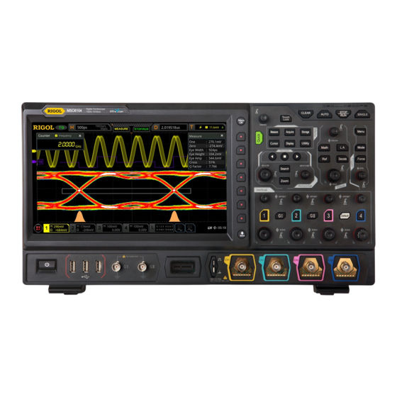
This manual gives you a quick review about the front and rear panel of MSO8000 series, the user interface, and the basic operation method. http:// For the latest version of this manual, download it from the official website of RIGOL ( www.rigol.com Publication Number... - Page 7 MSO8204 as an example to illustrate the functions and operation methods of MSO8000 series oscilloscope. No. of Max. Analog No. of Digital No. of AWG Model Analog Bandwidth Channels Channels Channels MSO8064 600 MHz MSO8104 1 GHz MSO8204 2 GHz Copyright ©RIGOL TECHNOLOGIES CO., LTD. All rights reserved.
-
Page 8: General Inspection
The consigner or carrier shall be liable for the damage to the instrument resulting from shipment. RIGOL would not be responsible for free maintenance/rework or replacement of the instrument. 2. Inspect the instrument In case of any mechanical damage, missing parts, or failure in passing the electrical and mechanical tests, contact your RIGOL sales representative. -
Page 9: Product Overview
Product Overview Product Overview MSO8000 series digital oscilloscope developed by RIGOL is a medium and high-end mixed signal digital oscilloscope designed based on UltraVision II platform built on our custom ASIC technology. With the analog bandwidth up to 2 GHz, the digital... - Page 10 LAN Interface USB DEVICE Interface USB HOST Interface HDMI Video Output 10M Reference Clock In/Out External Trigger Input Terminal (EXT TRIG) Trigger Output Interface (TRIG OUT) Kensington Security Lock Fuse AC Power Connector Copyright ©RIGOL TECHNOLOGIES CO., LTD. All rights reserved.
- Page 11 CH4 Status Label Trigger Position Prompt Message STOP/RUN Icon CH3 Status Label Horizontal Position CH2 Status Label Trigger Type CH1 Status Label Trigger Source Digital Channel Label and Waveform Trigger Level/Threshold Function Navigation Level Copyright ©RIGOL TECHNOLOGIES CO., LTD. All rights reserved.
-
Page 12: To Prepare For Use
Please use the power cord provided in the accessories to connect the oscilloscope to the AC power source, as shown in the figure below. Power Cord Connector Figure 7.2 To Connect to AC Power Copyright ©RIGOL TECHNOLOGIES CO., LTD. All rights reserved. -
Page 13: Turn-On Checkout
> Language to set the system language. To Connect the Probe RIGOL provides the passive probe, the active probe, and the logic probe for the MSO8000 Datasheet . For MSO8000 series. For specific probe models, please refer to Copyright ©RIGOL TECHNOLOGIES CO., LTD. All rights reserved. - Page 14 " and " ". Connect the active probe: Take RP7150 (active differential probe head) as an example. Figure 1. Connect the probe head to the preamp of the active probe, as shown in Copyright ©RIGOL TECHNOLOGIES CO., LTD. All rights reserved.
- Page 15 Connect the logic probe 1. Connect the output terminal of the logic probe to the digital channel input terminal on the front panel of the oscilloscope in the correct direction, as shown in Figure 7.6 Copyright ©RIGOL TECHNOLOGIES CO., LTD. All rights reserved.
-
Page 16: Function Inspection
To Prepare for Use 2. Connect the other terminal of the logic probe to the signal terminal under test. RIGOL's MSO8000 series has a standard configuration of a logic probe RPL2316. To apply to different application scenarios, RPL2316 provides three connection RPL2316 Logic Probe methods to connect the signal under test. -
Page 17: Probe Compensation
When the probes are used for the first time, you should compensate the probes to make them match the input channels of the oscilloscope. Non-compensated or poorly compensated probes may cause measurement inaccuracy or errors. The probe compensation procedures are as follows: Copyright ©RIGOL TECHNOLOGIES CO., LTD. All rights reserved. - Page 18 3. Use the probe compensation adjustment tool provided in the accessories to adjust the low-frequency compensation adjustment hole on the probe until the displayed waveform is consistent with the "Perfectly compensated" waveform shown in Figure 7.9 Copyright ©RIGOL TECHNOLOGIES CO., LTD. All rights reserved.
-
Page 19: Touch Screen Controls
Tap the close button at the upper-right corner of the message box to close the prompt window. • Tap other windows on the touch screen and operate on the windows. Figure 8.1 Tap Gesture Copyright ©RIGOL TECHNOLOGIES CO., LTD. All rights reserved. - Page 20 Drag the waveform to change its position or scale. • Drag the window controls to change the position of the window (e.g. numeric keypad). • Drag the marker to change the position of the marker. Figure 8.3 Drag Gesture Copyright ©RIGOL TECHNOLOGIES CO., LTD. All rights reserved.
-
Page 21: Rectangle Drawing
Figure 8.4 Rectangle Drawing Gesture(a) Figure 8.5 Rectangle Drawing Gesture(b) • Select "Trigger zone A": Draw the region for Trigger zone A; Open Trigger zone A: Open the "Zone Trig" menu. • Select "Trigger zone B": Copyright ©RIGOL TECHNOLOGIES CO., LTD. All rights reserved. - Page 22 Tap the "Draw rect" icon, if is displayed, it indicates that the waveform operation mode is enabled. By default, the waveform operation mode is enabled. Copyright ©RIGOL TECHNOLOGIES CO., LTD. All rights reserved.
-
Page 23: To Use The Built-In Help System
Help Options Help Display Area Figure 9.1 Help Information After opening the help interface, you can get its help information in the "Help Display Area" through the following three methods: Method 1: Copyright ©RIGOL TECHNOLOGIES CO., LTD. All rights reserved. - Page 24 If the menu item is grayed out, you cannot press the corresponding front-panel menu key to obtain the help information. What you can do is only to follow the above Method 2 or 3 to get the help information. Copyright ©RIGOL TECHNOLOGIES CO., LTD. All rights reserved.
-
Page 25: Parameter Setting Method
OK directly to confirm the input and close the numeric keypad. At this time, the unit of the parameter is the default unit. In the numeric keypad, you can also perform the following operations: Copyright ©RIGOL TECHNOLOGIES CO., LTD. All rights reserved. - Page 26 This method is applicable to the parameters with only two available options. The above method is commonly used for the parameter settings of the oscilloscope. For other methods of parameter settings, refer to details in User Guide of this instrument. Copyright ©RIGOL TECHNOLOGIES CO., LTD. All rights reserved.
-
Page 27: Fuse Replacement
WARNING To avoid electric shock, please ensure that the instrument has been turned off, the power source has been cut off, and the fuse to be used conforms to the fuse rating. Copyright ©RIGOL TECHNOLOGIES CO., LTD. All rights reserved. -
Page 28: Remote Control
The remote control can be realized by using SCPI (Standard Commands for Programmable Instruments) commands. MSO8000 series digital oscilloscope supports four ways of remote control: user-defined programming, PC software (e.g. RIGOL Ultra Sigma), VNC control, and Web Control. Copyright ©RIGOL TECHNOLOGIES CO., LTD. All rights reserved. -
Page 29: More Product Information
For more information about this instrument, refer to the relevant manuals by logging http://www.rigol.com in to the official website of RIGOL ( MSO8000 User Guide introduces the functions of the instrument and the operation methods, remote control methods, possible failures and solutions in using the instrument, the technical specifications, and order information;...
Need help?
Do you have a question about the MSO8104 and is the answer not in the manual?
Questions and answers