Table of Contents
Advertisement
Quick Links
DH-VOM* K1 / K9
INSTALLATION MANUAL
Manufacturer:
DHOLLANDIA US, L.L.C.
E-mail : Technical.US@dhollandia.com
270 Southridge Parkway
Bessemer City North Carolina, 28016
website : www.dhollandia.com
Read the manual in its entirety before operating the liftgate
Keep this manual in the vehicle cab, as reference for the driver and liftgate operator
Order ref: xxx Doc: FIT_US installation manual VOM_US EN_2023 Rev: 1 Date: SEPTEMBER 1, 2023
Advertisement
Table of Contents

Related Manuals for Dhollandia DH-VOM K1 Series


Summary of Contents for Dhollandia DH-VOM K1 Series
- Page 1 DH-VOM* K1 / K9 INSTALLATION MANUAL Manufacturer: DHOLLANDIA US, L.L.C. E-mail : Technical.US@dhollandia.com 270 Southridge Parkway Bessemer City North Carolina, 28016 website : www.dhollandia.com Read the manual in its entirety before operating the liftgate Keep this manual in the vehicle cab, as reference for the driver and liftgate operator...
-
Page 2: Table Of Contents
Platform pitch adjustment ................................ 32 12.2 Platform lock adjustment for manual open / closed position ....................33 12.3 Platform manual fold / unfold assist ............................33 12.4 Upper end stops ..................................33 LUBRICATION INSTRUCTIONS ..............................34 QUALITY CONTROL AND PDI ............................... 36 DHOLLANDIA... - Page 3 Prescribed torque values for bolts and nuts ..........................43 16.3 Electric and hydraulic requirements ............................44 16.4 Safe operator position on the platform ............................ 46 16.5 End note ....................................47 16.6 Basic wiring diagrams ................................47 16.7 Checklist for preventative maintenance and repair ......................... 47 DHOLLANDIA...
-
Page 4: Understanding Safety And Warning Signs
Many safety signs and symbols used in this manual are based on international standards, others refer to specific situations or actions. • Consult appendix 16.1 on page 41 for an overview of signs and symbols used in DHOLLANDIA manuals, and their meaning. Make sure you understand these signs and symbols prior to starting the installation. -
Page 5: Introduction, Contact Info And Disclaimers
NOTICE • Please confirm you have reviewed the most up-to-date version of this manual prior to operation of the associated DHOLLANDIA liftgate. See below for instructions to download the latest version of the manual. - Page 6 • DHOLLANDIA disclaims any liability for damage arising from modifications to the vehicle in its entirety as a result from installation. All modifications to the vehicle must be done in accordance to instructions issued by the vehicle and body manufacturer.
-
Page 7: Safety Precautions For Operation
• Safety instructions are a matter of progressive insight. The basics are listed in this manual, but contact the national DHOLLANDIA distributor for a copy of the latest set of instructions [see contact info on page 4], or download the latest edition from the DHOLLANDIA website: www.dhollandia.com →... - Page 8 ALWAYS confirm you have reviewed the most up-to-date version of these manuals prior to installation and operation of the associated DHOLLANDIA liftgate. • In case of doubt, ALWAYS contact the national DHOLLANDIA distributor for further advice, prior to continuing. • ALWAYS wear appropriate Personal Protective Equipment. This includes but may not be limited to: safety glasses with side guards or a wrap-around face shield;...
-
Page 9: Liftgate Terminology
Make sure the main battery power is disconnected while installing the liftgate. Connect the battery power to the liftgate only when the installation is completed, or as required in the installation instructions. • DHOLLANDIA liftgates are designed as a bolt-on system, and don’t require any welding. See 16.2 on page 43 for prescribed torque values. •... -
Page 10: Installation Parameters Terminology
Total depth from the front face of the column to the outboard face of the platform ltow lift total outside width Outside width across the columns and any additional brackets (e.g., energy track for hydraulic hoses, etc.) DHOLLANDIA... - Page 11 Center width between the mounting holes in L and R column lift column depth Depth of the column profile (longitudinal) lift column thickness Thickness of the column profile (lateral) mcog mounting clearance columns to ground Ground clearance under the lift columns platform depth Overall platform depth DHOLLANDIA...
-
Page 12: Getting Started
• DHOLLANDIA disclaims any liability for damage arising from modifications to the vehicle in its entirety as a result from installation. All modifications to the vehicle must be done in accordance to instructions issued by the vehicle and body manufacturer. -
Page 13: Installation Dimensions And Guidelines
• The LADEN vehicle floor height is measured on a FULLY LOADED vehicle. INSTALLATION RESOURCES • If in doubt on any installation parameters given, please reach out to your local DHOLLANDIA distributor. See contact info on page 4. DHOLLANDIA... -
Page 14: Important Guidelines
• The DHOLLANDIA column lifts consist of a wide range of different executions and are offered with a multitude of options to adapt the liftgate to the client’s specific needs. They are installed on a wide variety of different vehicles, often personalized by the body builder. -
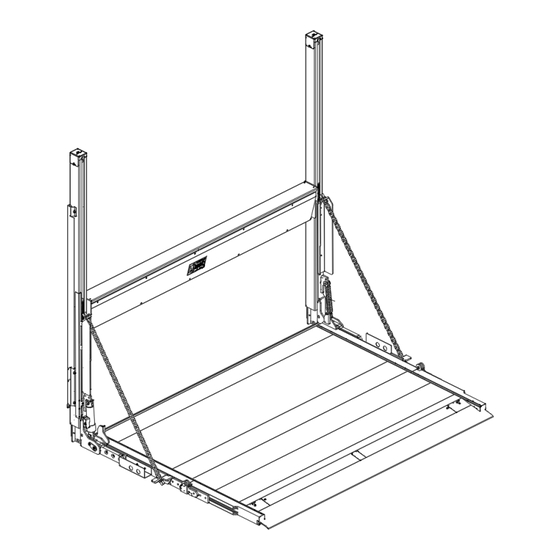
Page 15: Mounting Of The Lift Frame (Premounted Platform)
4” (100 mm) overhang. These alignment tubes will help align the platform with the bed extension. • Install at minimum, a 300 lbs (136 kg) counterweight on the tube channels to prevent them from moving during installation. Or tack-weld the tube channels temporarily to the rear sill and floor of the vehicle. DHOLLANDIA... - Page 16 • After installation, the platform will deploy at 90* from the lift columns. • The platform is designed to be level with the ground, and not the vehicle floor. DHOLLANDIA...
-
Page 17: Welded Installation
• Make sure that the lift frame and cylinder beam are properly centered, square, plumb, level, and true to the vehicle body. • Use suitable C-clamps to secure the lift columns and cylinder beam in the final working position. DHOLLANDIA... - Page 18 Verify that all nylon slide pads have remained undamaged. Replace them if required. See contact info on page 4. • Verify that no metal chips, welding spares and slag have fallen inside the columns or cylinder beam. Clean out if required DHOLLANDIA...
- Page 19 Weld the lift columns to the rear frame of the vehicle body in accordance with all welding instructions in this manual. • Disregard could lead to a fall of the liftgate and its load, and may put the operator and bystanders at risk of serious personal injury or death. DHOLLANDIA...
-
Page 20: Bolt-On Installation
Fasten the mounting bolts with the prescribed torque. See 16.2 on page 43 (see values for “shear”). • Disregard could lead to a fall of the liftgate and its load, and may put the operator and bystanders at risk of serious personal injury or death. DHOLLANDIA... - Page 21 • To position the bolts, compromise between the instructions below and the construction of the rear sill of the loading floor. DHOLLANDIA...
-
Page 22: General Remarks
This includes situations where the ground surrounding the liftgate may be lower in elevation than the ground surrounding the vehicle. • After cutting the lift columns, shape and deburr the leading edge to ensure a smooth sliding surface for the slide pads. DHOLLANDIA... -
Page 23: Installation Of Electrical Controls
Prevent ingress of water into the pump unit and control boxes if applicable. • Route and secure cables downward, forming a “drip loop” as they exit the pump unit. • Connect the wires of the cable to the connection points in the pump unit as per wiring diagram below. DHOLLANDIA... - Page 24 DHOLLANDIA...
-
Page 25: Installation Of The Cabin Switch (Oae510.15 - E0393.S.15)
• The switch interrupts power from the vehicle batteries to the connection block inside the power pack. • This cable wiring for the cabin switch must be a minimum of 16 AWG (1.5mm ) to avoid voltage drop issues. DHOLLANDIA... -
Page 26: Installation Of Extra Controls - 2 Button Remote Control (Oae001 - E0787.2.M.s)
Prevent ingress of water into the pump unit and control boxes if applicable. • Route and secure cables downward, forming a “drip loop” as they exit the pump unit. • Connect the wires of the cable to the connection points in the pump unit, as per wiring diagram below. DHOLLANDIA... - Page 27 DHOLLANDIA...
-
Page 28: Electrical Installation
To ensure the reliability of the lift over many years after installation, check and make sure the cables pass through the back plate of the pump unit, are properly mounted, and will seal the inside of the pump. • DHOLLANDIA disclaims liability for any personal injury or property damage that results from improper or negligent installation. (+) battery cable Motor solenoid... - Page 29 Use a second wrench so the ground terminal instructions in section 9 on page 22. does not turn in its place. Turning the terminal in place will damage the grounding inside the motor and render it inoperable. DHOLLANDIA...
- Page 30 • Make sure this conduit is suitable for automotive purposes, and its class is adapted to possible sources of heat nearby. In case of doubt, contact your national DHOLLANDIA distributor. See page 4 for contact info. • Fasten all connections at both ends of the cables thoroughly. Loose connections can lead to bad contacts and overheating, followed by premature failing of the electrical circuit.
-
Page 31: Liftgate Schematic
• A general hydraulic and electric schematic for the DH-VOM* series is given below. Please note that only main external controls are included in this instruction. For more detailed instructions on optional controls, see 9 from page 22 onwards. DHOLLANDIA... -
Page 32: Putting The Liftgate Into Service
The installer MUST remain vigilant and stay out of the range of motion of the platform and the moving parts of the lift as long as the hydraulic circuits have not been bled and all functions duly tested. DHOLLANDIA... -
Page 33: Platform Orientation
Falling cargo will put the operator and any bystanders at serious risk of bodily injury and death. • Therefore, it is important that the pitch of the platform is adjusted correctly to conform with the instructions in this manual. DHOLLANDIA... -
Page 34: Platform Lock Adjustment For Manual Open / Closed Position
Therefore, the tension in the bar should only be adjusted by someone who has been specifically trained to do so. It is NOT a user serviceable part. • Please contact Dhollandia for further advice if platform fold / unfold adjustment is required. See contact info on page 4. 12.4 UPPER END STOPS •... -
Page 35: Lubrication Instructions
Refer to appendix 16.7 from page 47 onwards for the relevant maintenance checklist. Download any grease plans from the website at: www.dhollandia.com → Country & language selection → Downloads → Maintenance & Repair → Grease plans → … select required plan •... - Page 36 DHOLLANDIA...
-
Page 37: Quality Control And Pdi
16 x 16” (400 mm) at a safe distance of 10” (250 mm) removed from the hazardous crushing area between the inboard edge of the platform and the rear sill of the vehicle body. • Work through the CHECKLIST FOR THE PRE-DELIVERY- INSPECTION (PDI) TEST. See Appendix 16.7 on page 47. • Complete the practical tests indicated therein. DHOLLANDIA... - Page 38 • Adjust the pressure if too high or too low, seal the pressure relief valve after that. • If in doubt how to adjust the pressure relief valve, contact your national DHOLLANDIA distributor for help. See contact info on page 4. •...
-
Page 39: Decals
Note: the decals marked as “EXAMPLE” can vary in function of the maximum rated capacity of the liftgate, or the chosen type of external control box. NOTICE • Remove any unwanted debris or residue from surfaces before installing any of the decals to ensure proper adhesion. DHOLLANDIA... - Page 40 EF0580.EN.CAP ❶ ❸ EF0565.EN ❺ EF0616.US EF0590.EN ❹ ❻ Loading decal (with SNR) ❽ EF0562.EN EF0567.EN ❼ LIFTGATE DECALS USED AND AFFIXED IN AREAS OTHER THAN THE REAR OF THE VEHICLE: Serial tag for Owner’s Manual EF0814.EN.US EF0816.ENFR EF0817.ENFR DHOLLANDIA...
-
Page 41: Use Of The 'Warning. Liftgate Out Of Service. Do Not Attempt To Operate' Sign
See examples below. • The liftgate must not be used again until it has been serviced or repaired by a qualified service technician. • Place this decal along with the User Manual in the glove box compartment of the vehicle. EF0586.US DHOLLANDIA... -
Page 42: Appendix
16.1 MEANING OF THE SAFETY AND WARNING SIGNS WARNING signs MANDATORY ACTION signs Overview and keep visual control over the working Contact your regional DHOLLANDIA distributor. area of the hydraulic ramp at all times. General warning sign used to alert the user to Consult the DHOLLANDIA website. - Page 43 / or Switch between external and internal controls. cabin switch. This is an operation to be executed manually (as opposed to an electrical function controlled by means of one of the control units). DHOLLANDIA...
-
Page 44: Prescribed Torque Values For Bolts And Nuts
A fall of the liftgate off the chassis can damage the liftgate and / or vehicle chassis and can cause serious bodily injury or death to the operator and any bystanders. • Therefore, it is essential that the mount plates are installed following the instructions of this manual. DHOLLANDIA... -
Page 45: Electric And Hydraulic Requirements
• The applicable wiring diagrams are saved at the inside of the main external control box and can be found there for reference. • A copy of the wiring diagrams can also be obtained from the national DHOLLANDIA distributor [see contact info on page 4];... - Page 46 It is important to follow these guidelines with due care. A lot of oils or fluids used in automotive industry, such as transmission fluids and ATF oils, are not suitable for liftgate use. DHOLLANDIA has not tested the potential consequences of oils and fluids with deviating specifications and cannot be held responsible or legally liable for any damage to the liftgate caused by the replenishment with non-compatible oils or fluids;...
-
Page 47: Safe Operator Position On The Platform
3 points of contact while travelling on the platform, in accordance with the operation manual.] • The handgrip is normally foreseen by the body builder as part of the design of the box. A DHOLLANDIA alternative can be ordered with spare part ref. M1406. -
Page 48: End Note
16.5 END NOTE • DHOLLANDIA would like to thank you for using our products and leave you with this final notice and warning. • Additional information about this liftgate and many other DHOLLANDIA products is available at the following link: http://www.dhollandia.com/...
Need help?
Do you have a question about the DH-VOM K1 Series and is the answer not in the manual?
Questions and answers