
Related Manuals for Lester Links 29840


Summary of Contents for Lester Links 29840
- Page 1 USER’S MANUAL Model 29840 Important Safety, Installation, Operation, and Maintenance Instructions www.LesterElectrical.com...
-
Page 2: Table Of Contents
TABLE OF CONTENTS TABLE OF CONTENTS ......................2 IMPORTANT SAFETY INSTRUCTIONS ................... 3 NOTICE: ............................. 5 1. SYSTEM OVERVIEW ......................5 2. EXTERNAL POWER SUPPLY (EPS) FEATURES ............... 5 2.1 VEHICLE INTERLOCK ....................5 2.2 LONG-TERM STORAGE CHARGE ................5 3. -
Page 3: Important Safety Instructions
IMPORTANT SAFETY INSTRUCTIONS SAVE THESE INSTRUCTIONS – This manual contains important safety and operating instructions. Before using the EPS, read all instructions and cautionary markings on the EPS, battery, and product using battery. LOOK FOR THIS SYMBOL TO POINT OUT SAFETY PRECAUTIONS. IT MEANS: BE ALERT—YOUR SAFETY IS INVOLVED. - Page 4 WARNING: HAZARD OF ELECTRIC SHOCK. WARNING: LEAD-ACID BATTERIES GENERATE EXPLOSIVE GASES. TO PREVENT ARCING OR BURNING NEAR BATTERIES, DO NOT DISCONNECT EPS DC CORD FROM BATTERIES WHEN THE EPS IS OPERATING. KEEP SPARKS, FLAME, AND SMOKING MATERIALS AWAY FROM BATTERIES. WARNING: ALWAYS SHIELD EYES WHEN WORKING NEAR BATTERIES.
-
Page 5: Notice
Club Car® and PowerDrive® are registered trademarks of Club Car, Inc. 1. SYSTEM OVERVIEW The Lester Electrical Links Series Model 29840 EPS unit functions as an integral part of Club Car® Excel, IQ, PowerDrive® and PowerDrive® Plus electrical systems. Because the EPS is controlled by the vehicle onboard computer, it will work with only Excel System, IQ System, PowerDrive®, and PowerDrive®... -
Page 6: Battery Warning Light
3. BATTERY WARNING LIGHT The vehicle features a dash mounted warning light (above the steering column) that, when the vehicle is in operation, indicates low battery voltage or, when the vehicle is being charged, indicates a charging problem. The battery warning light is controlled by the onboard computer. See following NOTE. NOTE: Beginning with the 1998 model year, the onboard computer LED became part of the battery warning light rather than being mounted in the computer itself, and the warning light lens color... - Page 7 DANGER: • THE CHARGING AREA MUST BE VENTILATED. HYDROGEN LEVEL IN THE AIR MUST NEVER EXCEED 2%. THE TOTAL VOLUME OF AIR IN THE CHARGING AREA MUST BE CHANGED FIVE TIMES PER HOUR. EXHAUST FANS SHOULD BE LOCATED AT THE HIGHEST POINT OF THE ROOF.
-
Page 8: Ac Input
Mount EPS by setting it on a shelf, wall mount with keyhole, or hang securely from ceiling by the handle. Do not hang EPS upside down. Ensure that the EPS ventilation slots are unobstructed and that there is adequate ventilation. 7. -
Page 9: Proper Care Of Deep Cycle Motive Power Patteries
8. PROPER CARE OF DEEP CYCLE MOTIVE POWER PATTERIES Motive power battery packs are subjected to severe deep-cycle duty on a daily basis. Although these batteries are designed to withstand such duty, the following precautions must be observed to obtain good performance and maximum cycle life. -
Page 10: Eps Operation
9. EPS OPERATION WARNING: TO REDUCE THE RISK OF AN ELECTRIC SHOCK, CONNECT ONLY TO A SINGLE-PHASE, PROPERLY GROUNDED (3-WIRE) OUTLET. REFER TO GROUNDING INSTRUCTIONS. CAUTION: MAKE SURE THE BATTERY IS A RECHARGEABLE DEEP-CYCLE BATTERY WITH THE PROPER RATED VOLTAGE FOR THIS EPS UNIT. DANGER: TO PREVENT ELECTRICAL SHOCK, DO NOT TOUCH UNINSULATED PARTS OF THE EPS DC OUTPUT CONNECTOR, BATTERY CONNECTOR, OR BATTERY TERMINALS. - Page 11 ELECTRICAL CONNECTION. FIRE OR PERSONAL INJURY CAN RESULT. HAVE IT REPLACED BY A QUALIFIED SERVICE PERSON IMMEDIATELY. FAILURE TO FOLLOW THESE INSTRUCTIONS COULD RESULT IN DAMAGE TO THE EPS CORD, THE PLUG, AND (OR) THE VEHICLE RECEPTACLE. WARNING: • DO NOT USE AN EPS IF: - THE PLUG IS TOO LOOSE OR DOES NOT MAKE A GOOD CONNECTION.
-
Page 12: Eps Plug And Receptacle
battery life, electric vehicles should always be recharged after 40 to 50 energy units of discharge or each night in order to avoid deep discharging the batteries. Charging between rounds will also extend battery life. If the charge system does not appear to be operating properly, or if the batteries appear to be weak, contact your distributor/dealer. -
Page 13: User Interface
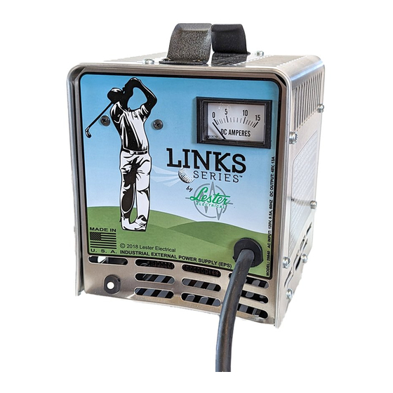
9.2 User Interface The user interface (Figure 9.2-1) includes an ammeter for monitoring the DC output current of the EPS unit. The user interface also includes an AC input circuit breaker. Figure 9.2-1: Links Series Model 29840 User Interface User’s Manual Links Series Model 29840 13 of 18... -
Page 14: Maintenance
10. MAINTENANCE WARNING: DISCONNECT BOTH AC AND DC POWER FROM THE EPS UNIT BEFORE PERFORMING ANY MAINTENANCE. CONTACT WITH LIVE COMPONENTS WITHIN THE EPS UNIT COULD CAUSE ELECTRICAL SHOCK, SERIOUS INJURY, OR DEATH. CAUTION: KEEP EPS UNIT CLEAN AND DRY, INSIDE AND OUT. FAILURE TO DO SO MAY CAUSE DAMAGE OR FAILURE OF EPS. -
Page 15: Troubleshooting And Service
11. TROUBLESHOOTING AND SERVICE CAUTION: DO NOT DISASSEMBLE THE EPS UNIT. TAKE IT TO A QUALIFIED SERVICE TECHNICIAN WHEN SERVICE OR REPAIR IS REQUIRED. INCORRECT REASSEMBLY MAY RESULT IN A RISK OF ELECTRIC SHOCK OR FIRE. DANGER: TO REDUCE THE RISK OF ELECTRIC SHOCK, ALWAYS DISCONNECT BOTH THE POWER SUPPLY CORD AND THE OUTPUT CORD BEFORE ATTEMPTING ANY MAINTENANCE OR SERVICE. -
Page 16: Service Parts
12. SERVICE PARTS Figure 12-1: Links Series Model 29840 Service ISO View SERVICE PARTS LIST Service Part Description Fuse Assembly 30784S Relay Board Assembly 26150S Kit, Diode Assemblies 38463S AC Circuit Breaker 31847S Ammeter 31158S AC Cordset Kit 21307-06S DC Cordset Kit 42541S User’s Manual Links Series Model 29840... -
Page 17: Wiring Diagram
13. WIRING DIAGRAM 14. SPECIFICATIONS PART NUMBER 29840 AC INPUT AC voltage: (volts) 105-128 Frequency: (hertz) AC current (amps) AC wattage (watts) 1140 DC OUTPUT DC voltage (start of charge cycle) DC current (start of charge cycle) 14.5 DC voltage (end of charge cycle) DC current (amps) (end of charge cycle) DIMENSIONS / WEIGHT 7.8 in. - Page 18 Represented By: 42567A User’s Manual Links Series Model 29840 18 of 18...
Need help?
Do you have a question about the Links 29840 and is the answer not in the manual?
Questions and answers
Will this charger work on AGM batteries