
Related Manuals for Lester X-Series SCR


Summary of Contents for Lester X-Series SCR
- Page 1 *37414* USER’S MANUAL Industrial Battery Charger Important Safety, Installation, Operation, and Maintenance Instructions www.LesterElectrical.com...
-
Page 2: Table Of Contents Charger Ratings Label
CHARGER RATINGS LABEL The ratings label is located on the back of the charger. The label provides the model (MODEL), serial number (SERIAL NO.), AC input configuration (AC VOLTS, AC AMPS, PHASE and HERTZ) and DC output specifications (CELLS, DC VOLTS, DC AMPS and AMP-HRS) of the charger. TYPE indicates the factory-configured battery type and if the charger is configured for on-board operation. -
Page 3: Table Of Contents
TABLE OF CONTENTS CHARGER RATINGS LABEL ....................2 TABLE OF CONTENTS ......................3 1. INTRODUCTION ........................6 2. RECEIVING THE CHARGER ....................6 3. STORAGE ..........................6 4. BATTERY TYPE ........................6 5. OFF-BOARD (SHELF) VERSUS ON-BOARD (BUILT-IN) CHARGERS ......7 ... -
Page 4: Important Safety Instructions
IMPORTANT SAFETY INSTRUCTIONS SAVE THESE INSTRUCTIONS – This manual contains important safety and operating instructions. Before using battery charger, read all instructions and cautionary markings on battery charger, battery, and product using battery. LOOK FOR THIS SYMBOL TO POINT OUT SAFETY PRECAUTIONS. IT MEANS: BE ALERT—YOUR SAFETY IS INVOLVED. -
Page 5: Save These Instructions
WARNING: HAZARD OF ELECTRIC SHOCK. WARNING: LEAD-ACID BATTERIES GENERATE EXPLOSIVE GASES. TO PREVENT ARCING OR BURNING NEAR BATTERIES, DO NOT DISCONNECT DC CHARGING CORD FROM BATTERIES WHEN THE CHARGER IS OPERATING. PUSH THE “STOP/START” BUTTON TO TURN CHARGER OFF. KEEP SPARKS, FLAME, AND SMOKING MATERIALS AWAY FROM BATTERIES. WARNING: ALWAYS SHIELD EYES WHEN WORKING NEAR BATTERIES. -
Page 6: Introduction
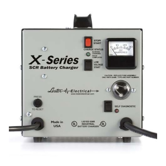
1. INTRODUCTION This X-Series battery charger is an advanced, microprocessor-based, silicon-controlled rectifier (SCR) charger designed to optimize both daily battery capacity and overall battery life. It plugs directly into standard 120V, 15A, 60 Hz AC outlets/receptacles for use in off-board (shelf) or on-board (built-in) applications. The charger is natural convection cooled with no moving parts. -
Page 7: Off-Board (Shelf) Versus On-Board (Built-In) Chargers
Part Number Battery Profile Code Battery Profile Wet, standard AGM, standard Gel, standard Figure 4-1: Standard Battery Profile Codes and Their Corresponding Battery Profiles To change the active battery profile on your charger, remove the charger cover and position the jumper as shown in Figure 4-2. -
Page 8: Off-Board Chargers
5.1 Off-Board Chargers Off-board chargers are designed to be used in shelf or portable applications. They include rubber feet. If the AC input plug is connected to AC power, a new charge cycle automatically starts when the DC output is connected to a battery pack of the proper voltage. -
Page 9: On-Board Mounting
6.1 On-Board Mounting On-board X-Series chargers are designed to be mounted on electric vehicles/equipment. They include steel feet with a pattern that provides numerous mounting options. A dimensional drawing of the on-board mounting pattern is provided in Figure 6.1-1. Figure 6.1-1: On-Board Mounting Pattern 7. -
Page 10: Dc Output
Figure 7-1: Grounding Methods (NOTE: Use of an adapter as shown in Figures B and C is NOT permitted in Canada) Use of an extension cord with the charger should be avoided. Use of an improper extension cord could result in a risk of a fire and electrical shock. -
Page 11: Proper Care Of Deep-Cycle Motive Power Batteries
9. PROPER CARE OF DEEP-CYCLE MOTIVE POWER BATTERIES Motive power batteries are subjected to severe deep-cycle duty on a daily basis. Although these batteries are designed to withstand such duty, the following precautions must be observed to obtain good performance and maximum cycle life. -
Page 12: Charger Operation
10. CHARGER OPERATION WARNING: TO REDUCE THE RISK OF AN ELECTRIC SHOCK, CONNECT ONLY TO A SINGLE-PHASE, PROPERLY GROUNDED (3-WIRE) OUTLET. REFER TO GROUNDING INSTRUCTIONS. CAUTION: MAKE SURE THE BATTERY IS A RECHARGEABLE DEEP-CYCLE BATTERY WITH THE PROPER RATED VOLTAGE FOR THIS CHARGER. DANGER: TO PREVENT ELECTRICAL SHOCK, DO NOT TOUCH UNINSULATED PARTS OF THE CHARGER DC OUTPUT CONNECTOR, BATTERY CONNECTOR, OR BATTERY TERMINALS. - Page 13 2. Connect the charger DC output connector to the battery pack connector by firmly grasping both connectors and plugging them straight together. The charger will start automatically, which is indicated by the blinking Charge Status LED on the user interface (on for approximately 1 second followed by off for approximately 1 second).
-
Page 14: User Interface
6. If the charger is in a post-charge mode, press the Stop/Start button on the charger user interface to terminate the post-charge mode, which is indicated by the solid illumination of the Charge Status LED. 7. Disconnect the charger AC input plug from the outlet. 8. -
Page 15: Low Voltage Start
10.2 Low Voltage Start The Low Voltage Start button manually starts a charge cycle for a battery with a voltage too low to automatically start (as low as 1V). You should press and hold the button for 5 to 10 seconds. If the battery voltage is 1V or above, the Charge Status LED will begin blinking while you are holding the button. -
Page 16: Lockout/Interlock Relay Option
DC Output A DC output issue exists. Ensure that the charger DC fuse on the user interface is not blown. Otherwise, the charger is not functioning properly. It is possible that the charger is still able to charge, but with reduced current. -
Page 17: Troubleshooting And Service
13. TROUBLESHOOTING AND SERVICE CAUTION: DO NOT DISASSEMBLE THE CHARGER. TAKE IT TO A QUALIFIED SERVICE TECHNICIAN WHEN SERVICE OR REPAIR IS REQUIRED. INCORRECT REASSEMBLY MAY RESULT IN A RISK OF ELECTRIC SHOCK OR FIRE. DANGER: TO REDUCE THE RISK OF ELECTRIC SHOCK, ALWAYS DISCONNECT BOTH THE POWER SUPPLY CORD AND THE OUTPUT CORD BEFORE ATTEMPTING ANY MAINTENANCE OR SERVICE. - Page 18 WIRING DIAGRAMS MODEL #27020 ONLY X-Series 18 of 20 User’s Manual...
-
Page 19: Limited Warranty
Lester Electrical warrants each new Lester Battery Charger for defects in material and workmanship for a period of two (2) years from the date of manufacture of the complete unit. Repairs can be made at the Lester factory. To do so, first obtain a "Return Material Authorization"... - Page 20 *37414* Represented By: 37414H X-Series 20 of 20 User’s Manual...
Need help?
Do you have a question about the X-Series SCR and is the answer not in the manual?
Questions and answers
When we plug the charger in we here a click and the red and light just flash but no output
If the Lester X-Series SCR charger clicks and the red light flashes but shows no output, it could indicate an issue detected by the self-diagnostic system. Possible causes include:
1. Battery Voltage Issue – The battery voltage may be too low (overly discharged) or too high (incorrectly sized). Ensure the battery matches the charger's specifications.
2. Timer Fault – The maximum charge cycle timer may have expired, or the maximum allowable amp-hours returned has been reached. Verify the battery is in good condition and within the charger's amp-hour range.
3. Control Board Issue – The control board may not be functioning properly.
4. Current Sense Issue – The current sensing component may be malfunctioning.
5. AC Input Issue – There may be a problem with the AC power supply. Check the charger’s AC power cord.
To resolve the issue, check the battery connection, ensure the battery meets the charger’s specifications, and verify the AC power supply is functioning correctly.
This answer is automatically generated