
Related Manuals for Lester E - Series SCR


Summary of Contents for Lester E - Series SCR
- Page 1 *37324* USER’S MANUAL Industrial Battery Charger Important Safety, Installation, Operation, and Maintenance Instructions www.LesterElectrical.com...
-
Page 2: Table Of Contents Charger Ratings Label
CHARGER RATINGS LABEL The ratings label is located on the back of the charger. The label provides the model (MODEL), serial number (SERIAL NO.), AC input configuration (AC VOLTS, AC AMPS, PHASE and HERTZ) and DC output specifications (CELLS, DC VOLTS, DC AMPS and AMP-HRS) of the charger. TYPE indicates the factory-configured battery type and if the charger is configured for on-board operation. -
Page 3: Table Of Contents
TABLE OF CONTENTS CHARGER RATINGS LABEL ....................2 TABLE OF CONTENTS ......................3 IMPORTANT SAFETY INSTRUCTIONS ................... 4 1. INTRODUCTION ........................6 2. RECEIVING THE CHARGER ....................6 3. STORAGE ..........................6 4. BATTERY TYPE ........................6 ... -
Page 4: Important Safety Instructions
IMPORTANT SAFETY INSTRUCTIONS SAVE THESE INSTRUCTIONS – This manual contains important safety and operating instructions. Before using battery charger, read all instructions and cautionary markings on battery charger, battery, and product using battery. LOOK FOR THIS SYMBOL TO POINT OUT SAFETY PRECAUTIONS. IT MEANS: BE ALERT—YOUR SAFETY IS INVOLVED. -
Page 5: Save These Instructions
WARNING: HAZARD OF ELECTRIC SHOCK. WARNING: LEAD-ACID BATTERIES GENERATE EXPLOSIVE GASES. TO PREVENT ARCING OR BURNING NEAR BATTERIES, DO NOT DISCONNECT DC CHARGING CORD FROM BATTERIES WHEN THE CHARGER IS OPERATING. KEEP SPARKS, FLAME, AND SMOKING MATERIALS AWAY FROM BATTERIES. WARNING: ALWAYS SHIELD EYES WHEN WORKING NEAR BATTERIES. -
Page 6: Introduction
1. INTRODUCTION This E-Series battery charger is an advanced, microprocessor-based, silicon-controlled rectifier (SCR) charger designed to optimize both daily battery capacity and overall battery life. It plugs directly into standard 120V, 15A, 60 Hz AC outlets/receptacles for use in off-board (shelf) or on-board (built-in) applications. The charger is natural convection cooled with no moving parts. -
Page 7: Off-Board (Shelf) Versus On-Board (Built-In) Chargers
Part Number Battery Profile Code Battery Profile Wet, standard AGM, standard Gel, standard Figure 4-1: Standard Battery Profile Codes and Their Corresponding Battery Profiles To change the active battery profile on your charger, remove the charger cover and position the jumper as shown in Figure 4-2. -
Page 8: Off-Board Chargers
5.1 Off-Board Chargers Off-board chargers are designed to be used in shelf or portable applications. They include rubber feet. If the AC input plug is connected to AC power, a new charge cycle automatically starts when the DC output is connected to a battery pack of the proper voltage. -
Page 9: Ac Input
Figure 6.1-1: On-Board Mounting Pattern 7. AC INPUT This charger must be connected to a single-phase nominal 120 Vac, 60 Hz AC power source with a voltage of 110 Vac to 132 Vac (charge times increase at lower AC voltages). The frequency must be 57 Hz to 63 Hz. Circuit breaker or fuse protection for the AC outlet to which the charger is connected should allow 15A per charger. -
Page 10: Dc Output
Figure 7-1: Grounding Methods (NOTE: Use of an adapter as shown in Figures B and C is NOT permitted in Canada) Use of an extension cord with the charger should be avoided. Use of an improper extension cord could result in a risk of a fire and electrical shock. -
Page 11: Proper Care Of Deep-Cycle Motive Power Batteries
9. PROPER CARE OF DEEP-CYCLE MOTIVE POWER BATTERIES Motive power battery packs are subjected to severe deep-cycle duty on a daily basis. Although these batteries are designed to withstand such duty, the following precautions must be observed to obtain good performance and maximum cycle life. -
Page 12: Charger Operation
10. CHARGER OPERATION WARNING: TO REDUCE THE RISK OF AN ELECTRIC SHOCK, CONNECT ONLY TO A SINGLE-PHASE, PROPERLY GROUNDED (3-WIRE) OUTLET. REFER TO GROUNDING INSTRUCTIONS. CAUTION: MAKE SURE THE BATTERY IS A RECHARGEABLE DEEP-CYCLE BATTERY WITH THE PROPER RATED VOLTAGE FOR THIS CHARGER. DANGER: TO PREVENT ELECTRICAL SHOCK, DO NOT TOUCH UNINSULATED PARTS OF THE CHARGER DC OUTPUT CONNECTOR, BATTERY CONNECTOR, OR BATTERY TERMINALS. - Page 13 3. If the charger must be disconnected from a battery pack while a charge cycle is in progress, disconnect the charger AC input connector from the AC outlet to stop the charge cycle before disconnecting the DC output connector from the battery pack. Do not disconnect the DC output connector from a battery pack while a charge cycle is in progress.
-
Page 14: User Interface
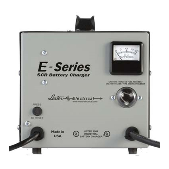
10.1 User Interface The user interface (Figure 10.1-1) includes an ammeter for monitoring the DC output current of the charger. The user interface also includes an AC input circuit breaker and DC output fuse. Figure 10.1-1: E-Series User Interface 11. LOCKOUT/INTERLOCK RELAY OPTION On-board E-Series chargers can be ordered with an optional internal relay that can be used to provide lockout/interlock functionality. -
Page 15: Check Charger Area
The charger requires minimal maintenance. It should be kept clean. Twice a year, or as often as the cleanliness of the area may dictate, the interior of the charger should be thoroughly blown clean with dry compressed air. The components of the charger are cooled by natural convection. If dust and debris are allowed to build up, they will restrict airflow and could cause components to overheat. - Page 16 SERVICE PARTS LIST 27070 26010 26040 25970 25940 26070 Service Part Description 12V 25A 24V 21A 24V 25A 36V 21A 36V 25A 48V 17A Fuse Assembly 08776S 08776S 08776S 08776S 08776S 08776S Relay Board Assembly 27105-09S 27105-10S 27105-10S 27105-11S 27105-11S 27105-12S SCR Assembly Kit 37204S...
- Page 17 WIRING DIAGRAM E-Series 17 of 20 User’s Manual...
-
Page 18: Limited Warranty
Lester Electrical warrants each new Lester Battery Charger for defects in material and workmanship for a period of two (2) years from the date of manufacture of the complete unit. Repairs can be made at the Lester factory. To do so, first obtain a "Return Material Authorization"... - Page 19 NOTES E-Series 19 of 20 User’s Manual...
- Page 20 *37324* Represented By: 37324G E-Series 20 of 20 User’s Manual...
Need help?
Do you have a question about the E - Series SCR and is the answer not in the manual?
Questions and answers