
Related Manuals for Teledyne AxCIS Series


Summary of Contents for Teledyne AxCIS Series
- Page 1 AxCIS Series AxCIS Contact Image Sensor User Manual Monochrome, CIS Line Scan sensors | cameras | frame grabbers | processors | software | vision solutions 03-032-25022-06 www.teledynedalsa.com...
- Page 2 All information provided in this manual is believed to be accurate and reliable. No responsibility is assumed by Teledyne DALSA for its use. Teledyne DALSA reserves the right to make changes to this information without notice. Reproduction of this manual in whole or in part, by any means, is prohibited without prior permission having been obtained from Teledyne DALSA.
-
Page 3: Table Of Contents
Contents AXCIS SERIES CAMERA FEATURES ____________________________________________ 1 ..........................1 ESCRIPTION CIS Optical Technology ....................... 1 Models ..........................2 CIS Features........................2 Automatic Sensor Alignment ....................2 Resolution ..........................3 Programmable Features ...................... 3 Applications ......................... 3 ................4 UMBERS AND... - Page 4 Imaging with Non-Square Object Pixels ................50 (AOI ) ....................51 SING REA OF NTEREST Reduce Image Data & Enhance Performance ..............51 Rules for Setting Areas of Interest ..................52 Steps to Setup Area of Interest for Each Section .............. 53 ............
-
Page 5: Axcis Series Camera Features
Over time, Teledyne DALSA will release the complete range of CIS modules from less than 300 mm to 1500 mm. The name of this product family is AxCIS. Initial offering has 400 and 800 mm scan widths at 300, 450, 600 or 900 dpi resolution (selectable) with optional integrated white LED illumination. -
Page 6: Models
The module automatically aligns each sensor's image data real time in x and y directions to form a continuous single, aligned image data. Overlap image data is removed. 2 • AxCIS Series Camera Features AxCIS Contact Image Sensor User Manual... -
Page 7: Resolution
Intensity control of optional LED arrays • Test patterns and diagnostics Applications • Flat panel inspection • Web and textile inspection • Printed circuit board inspection • 3D printer inspection • High-throughput applications AxCIS Series Camera Features • 3 AxCIS Contact Image Sensor User Manual... -
Page 8: Part Numbers And Software Requirements
Embedded within camera Sapera LT, including CamExpert GUI application and Latest version on the Teledyne DALSA Web site GenICam for Camera Link imaging driver For all models above, integrated lighting is available as an accessory. Each accessory is for a single LED light bar. -
Page 9: Performance Specifications
Performance Specifications Figure 1: AxCIS Monochrome Responsivity Graph Figure 2: AxCIS Color Responsivity Graph AxCIS Series Camera Features • 5 AxCIS Contact Image Sensor User Manual... - Page 10 Storage Humidity 15 to 85% Dust Ingress Protection IP rating IP60 (optical cavity) All specifications measured at 25 C over a temperature range of ±10 C unless specifically stated. 6 • AxCIS Series Camera Features AxCIS Contact Image Sensor User Manual...
-
Page 11: Industry Standard Reliability Qualifications
It is used where an industrial digital camera interfaces with a single or multiple frame grabbers and with data rates exceeding those supported by the LVDS based Camera Link standard. For more information see www.automate.org. AxCIS Series Camera Features • 7 AxCIS Contact Image Sensor User Manual... -
Page 12: Sfp+ Modules
10 Gbps XCVR modules can be added along with associated LC Fiber Optic cables as required to support image data bandwidth requirements. Note that the SFP+ XCVR are not included with the module and can be ordered separately from Teledyne DALSA or from another vendor who supplies compliant modules. -
Page 13: Mechanical Drawings
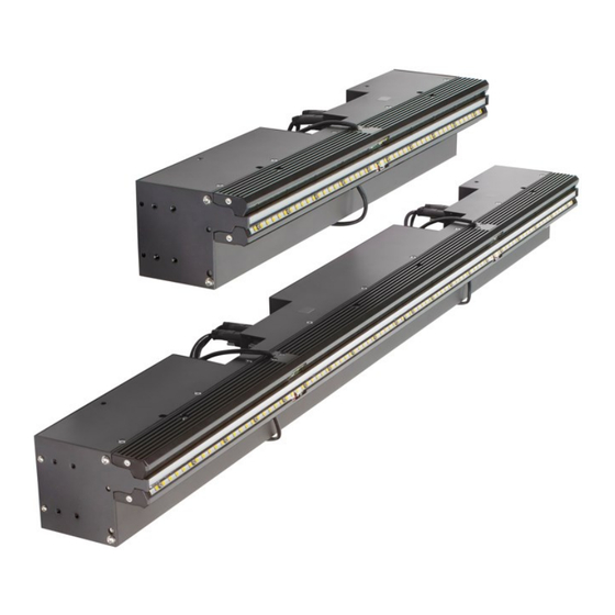
Mechanical Drawings AxCIS | Teledyne DALSA 3D stepfiles (.STP) are available for downloard from the Teledyne DALSA website: AX-FM-04B12A-00 & AX-FC-04B06T-00 Figure 4: 400MM General Overview AxCIS Series Camera Features • 9 AxCIS Contact Image Sensor User Manual... - Page 14 AX-FM-04B12A-00 Figure 5: & AX-FC-04B06T-00 400MM Mechanical Drawing (without optional LEDs) 10 • AxCIS Series Camera Features AxCIS Contact Image Sensor User Manual...
- Page 15 AX-FM-04B12A-00 Figure 6: & AX-FC-04B06T-00 400MM Mechanical Drawing (with optional LEDs) AxCIS Series Camera Features • 11 AxCIS Contact Image Sensor User Manual...
- Page 16 -FM-08A/B12H-00 Figure 7: AX 800mm CIS Mechanical Drawing General Overview 12 • AxCIS Series Camera Features AxCIS Contact Image Sensor User Manual...
- Page 17 -FM-08A/B12H-00 Figure 8: AX 800mm CIS Mechanical Drawing (without optional LEDs) AxCIS Series Camera Features • 13 AxCIS Contact Image Sensor User Manual...
- Page 18 -FM-08A/B12H-00 Figure 9: AX 800mm CIS Mechanical Drawing (with optional LEDs) 14 • AxCIS Series Camera Features AxCIS Contact Image Sensor User Manual...
-
Page 19: Precautions
Failure to do so could cause a burn. Minimum wire gauge is 22 AWG per pin. See the 26-pin High Density D-Sub Signal Details section for pinout information. AxCIS Series Camera Features • 15 AxCIS Contact Image Sensor User Manual... -
Page 20: Install & Configure Frame Grabber And Software
Install & Configure Frame Grabber and Software Because of the high bandwidth of AxCIS, a compatible Teledyne DALSA frame grabber Xtium2-CLHS FX8 (OR- A8S0-FX840), or equivalent, is recommended. For more details see the Teledyne DALSA website: http://www.teledynedalsa.com/en/products/imaging/frame-grabbers Figure 10: Xtium2-CLHS FX8 (OR-A8S0-FX840) CLHS Frame Grabber A GenICam compliant XML device description file is embedded with the module firmware. - Page 21 When using 3 or 4 AxCIS modules, select Four Camera Link HS cameras (note that modules will be limited to one LC cable only). The firmware configuration is set using the Teledyne DALSA Device Manager tool, included with the frame grabber driver installation, and available through the Windows Start menu.
-
Page 22: Setting Up For Imaging
3) LED status indicator. 4) Power and GPIO connector: +24 V DC, two Input, four Output, 26-pin HD D-Sub connector. 5) LED array#1 power. 6) LED array#2 power. 18 • AxCIS Series Camera Features AxCIS Contact Image Sensor User Manual... -
Page 23: Powering The Module
• Use high quality supplies in order to minimize noise NOTE If your power supply does not meet these requirements, then the module performance specifications are not guaranteed. AxCIS Series Camera Features • 19 AxCIS Contact Image Sensor User Manual... -
Page 24: Power And Gpio Connections
Signal Ground Do not use for power ground Reserved. Do not connect Power Ground All ground connections must be connected Power Ground All ground connections must be connected 20 • AxCIS Series Camera Features AxCIS Contact Image Sensor User Manual... - Page 25 CamExpert. The module will not power up below 21.6 V. A factory 2.5 meter power cable is available (accessory part number AC-CA-00424-00-R). Figure 16: Cable Accessory AC-CA-00424-00-R AxCIS Series Camera Features • 21 AxCIS Contact Image Sensor User Manual...
- Page 26 Figure 17: Cable Accessory AC-CA-00424-00-R Wiring Diagram For user's wanting to build custom cables, an available mating connector is an Amphenol CONEC (part #: 164A17019X) 22 • AxCIS Series Camera Features AxCIS Contact Image Sensor User Manual...
-
Page 27: Using Sapera Camexpert
The CamExpert application uses panes to organize the selection and configuration of camera files or acquisition parameters. The main window includes 3 main panes; Device Selector, Parameters and Display. Figure 18: CamExpert Frame Grabber Control Window AxCIS Series Camera Features • 23 AxCIS Contact Image Sensor User Manual... - Page 28 Output Message Pane: Displays messages from CamExpert or the device driver. At this point you are ready to start operating the camera, acquire images, set camera functions and save settings. 24 • AxCIS Series Camera Features AxCIS Contact Image Sensor User Manual...
-
Page 29: Establishing Module Communications
For the AxCIS 800 mm with two modules, CameraLink HS Mono #1 and #2 are available, which correspond to the Master and Child modules. Figure 19: CamExpert Device Selector AxCIS Series Camera Features • 25 AxCIS Contact Image Sensor User Manual... - Page 30 Also check that the frame grabber's Image Buffer Format is set appropriately to correspond to the module's Pixel Format. Figure 22: CamExpert Frame Grabber Image Buffer Format Feature 26 • AxCIS Series Camera Features AxCIS Contact Image Sensor User Manual...
-
Page 31: Establishing Data Integrity
If the test pattern is not correct, check the cable connections and the frame grabber setup; refer to the Test Patterns – What Can They Indicate? section for more information on troubleshooting. Figure 25: CamExpert Grab With Test Pattern 4. Disable the test pattern output. AxCIS Series Camera Features • 27 AxCIS Contact Image Sensor User Manual... -
Page 32: Camera Features
Camera Features This section is intended to be a progressive introduction to camera features, including explanations of how to use them effectively. Pixel Format See the section Image Format Category in Appendix A for GenICam features associated with this section and how to use them. - Page 33 For example, to change pixel format: • In Acquisition and Transfer Control category, click on the Acquisition Stop feature's field; the Acquisition Status will display "Not Acquiring". Figure 27: CamExpert Acquisition Stop Feature • In Image Format category, set Pixel Format to the required format. Figure 28: CamExpert Pixel Format Feature (monochrome device) •...
-
Page 34: Sensor Saturation
In addition, in the Image Buffer and ROI category, verify that the Image Buffer Format is set to the appropriate corresponding format. Figure 30: CamExpert Frame Grabber Image Buffer Format Feature (monochrome models) • In the camera's Acquisition and Transfer Control category, click on the Acquisition Start feature's field; the Acquisition Status will display "Acquiring". -
Page 35: Monochrome Module Specific Features
Monochrome Module Specific Features Dual Exposure Mode (HDR) Some inspection applications may have areas where specific features must be identified that have very bright and very dark areas within the same field of view. Optimizing for the bright areas may result in too much noise to detect features in dark areas and optimizing for the dark areas may result in saturating the image in bright areas. - Page 36 NOTE For monochrome models, when Dual Exposure mode is enabled (set using the Exposure Mode feature), the module outputs data to the frame grabber in a ‘planar’ format; the corresponding lines are output separately one after the other. For color models dual exposure mode is not available; however separate exposure times can be set for the Red / Blue and Green rows (see the Color Module Specific Features section).
-
Page 37: Color Module Specific Features
Color Module Specific Features The AxCIS color sensor has 3 rows of 14 um pixels for blue, green and red: Figure 35: AxCIS Color Sensor Rows Exposure Times The AxCIS color model supports separate exposure times for the Red / Blue rows and Green row; use the Exposure Time Selector, available in the Camera Control category, to select either Red / Blue or Green, then set the Exposure Time feature to the required exposure. -
Page 38: Row Gains
Figure 38: CamExpert Frame Grabber Image Buffer Format Row Gains Each color row can have its own gain applied. Use the Row Selector feature, available in the Camera Control category, to choose an individual row or All Rows, then use the Row Gain feature to specify the gain value. Figure 39: CamExpert Row Selector Feature 34 •... -
Page 39: Color Transformation Matrices
Color Transformation Matrices The RGB values output by the camera depend on the spectral responsivity of the camera and on the color temperature of the light source. For example, with a light that is more blue than red, the blues will be brighter and the reds dimmer. - Page 40 The generated .ccor file can then be uploaded to the AxCIS color module using the File Access Control dialog: Figure 41: CamExpert File Acces Control Dialog NOTE The factory color transformation matrix is enabled by default. This matrix was generated using the optional LED lighting;...
-
Page 41: Automatic White Balancing
Automatic White Balancing The Balance White Auto feature, available in the Camera Control category, is used to calculate the RGB gain adjustments, which are then applied to subsequent snaps or grabs. Click "Press..." to execute the automatic white balance function. The reference color component is automatically selected so that the minimum component’s gain becomes 1.00. -
Page 42: Synchronizing To Object Motion
Synchronizing to Object Motion Acquiring Images: Triggering the Camera Related Features: Trigger Mode, Trigger Source, Trigger Activation Several different methods can be used to trigger image acquisition in the camera: Internal Trigger The simplest method is to set the Trigger Mode feature, available in the Digitial IO Control category, to “Internal”. Figure 43: CamExpert Trigger Mode Feature This results in the camera being triggered by an internal timer, which can be adjusted using the Acquisition Line Rate feature. - Page 43 External Triggers When the Trigger Mode feature is set to “External”, the camera triggers come from a source selected through the Trigger Source feature. The available sources for the triggers are: • CLHS In: from the Camera Link HS frame grabber •...
- Page 44 If using a frame trigger, set the External Trigger category features as required for the trigger. Figure 47: CamExpert Frame Grabber External Trigger Feature Category Line Rate and Synchronization A continuous stream of encoder trigger pulses, synchronized to the object motion, establishes the line rate. The faster the object’s motion is, the higher the line rate.
- Page 45 Note: lower dpi enables higher possible line rates. For advice on your setup and achieving higher line rates, contact Teledyne DALSA customer support Internal Trigger Mode Minimum Line Rate The minimum line rate for internal trigger is 300 Hz. The modules include special features to prevent accumulation of dark current at very low and stopped line rates.
- Page 46 Measuring Line (Trigger) Rate Related Features: Measured Line Rate, Refresh Measured Line Rate The Measured Line Rate feature reads the actual line (trigger) rate being applied, externally or internally, to the camera. In CamExpert, in the Camera Control Category , pressing the Refresh Measured Line Rate field returns the current measured line rate.
-
Page 47: Establishing The Optimal Response
Establishing the Optimal Response An important AxCIS module performance characteristic is its responsivity and associated noise level at the system’s maximum line rate with the required illumination configuration. Responsivity and noise performance can be assessed using a stationary, plain white diffusing target using the optional LED illumination. -
Page 48: Saving & Loading A Prnu Set Only
Those areas of the image where high roll-off is present will show higher noise levels after flat field calibration due to the higher gain values of the correction coefficients. Flat field calibration can only compensate for up to an 8:1 variation. -
Page 49: Scan Direction
Scan Direction See the section Camera Control Category in Appendix A for GenICam features associated with this section and how to use them. Related Feature: Direction Source, Internal Scan Direction The AxCIS modules require the user to indicate the direction of travel of the object being imaged. The source of the scan direction is set using the Direction Source feature. -
Page 50: Camera Orientation
Camera Orientation The diagram below shows the orientation of forward and reverse with respect to the module body looking at its rear face. 1234 1234 1234 1234 1234 1234 1234 1234 1234 1234 1234 1234 1234 1234 1234 1234 Arrows 1234 1234 Denote... -
Page 51: Maintaining Image Alignment
Maintaining Image Alignment Adjusting the Encoder (EXSYNC) Input Image alignment is assured when the encoder (EXSYNC) pulses occur every 84 µm (300 dpi), 56 µm (450 dpi), 42 µm (600 dpi) or 28 µm (900 dpi) of object travel. The user may find it inconvenient to accurately create 84, 56, 42 or 28 µm encoder (EXSYNC) resolution, but may have another encoder source available at a different resolution. - Page 52 56 µm (450 dpi), 42 µm (600 dpi) or 28 µm (900 dpi). For more details on adjusting the shaft encoder refer to the Application Note for Multiplier Divider available from the Teledyne DALSA website at App Notes | Teledyne DALSA.
-
Page 53: Angle Correction: Imaging When Not Perpendicular To The Object Surface
Angle Correction: Imaging when not Perpendicular to the Object Surface Related Feature: Angle Correction, Acquisition Start and Acquisition Stop To obtain optimum imaging performance, the module may need to be angled away from perpendicular to the object surface. This changes the stagger distance between the sensor images, which affects the module’s alignment algorithms. -
Page 54: Imaging With Non-Square Object Pixels
Imaging with Non-Square Object Pixels Related Features: Encoder Resolution, Acquisition Start and Acquisition Stop In some applications the speed of the object and/or the available light may force the use of an object pixel size greater than 84 µm (300 dpi), 56 µm (450 dpi), 42 µm (600 dpi) or 28 µm (900 dpi). For example, if the inspection system is using a larger pixel to accommodate a faster web speed or achieve a longer integration time. -
Page 55: Using Area Of Interest (Aois)
Using Area of Interest (AOIs) Reduce Image Data & Enhance Performance See the section Image Format Category and Acquisition and Transfer Control Category in Appendix A for GenICam features associated with this section and how to use them Related Features: AOI Count, AOI Selector, AOI Offset, AOI Width, AcquisitionStart, AcquisitionStop and AcquisitionStatus If the module’s field of view includes areas that are not needed for inspection (also refer to the Flat Field Calibration Region of Interest section) then the user may want to ignore this unwanted image data. -
Page 56: Rules For Setting Areas Of Interest
Rules for Setting Areas of Interest The rules are dictated by how image data is organized for transmission over the available CLHS data lanes. The camera enforces these rules, truncating entered values where necessary. Table 16: AOI Specifications Module Number Step Size Minimum AOI Width Maximum AOI Width... -
Page 57: Steps To Setup Area Of Interest For Each Section
Steps to Setup Area of Interest for Each Section 1. Plan your AOIs. 2. Stop acquisition, using the Acquisition Stop feature. In CamExpert this feature is available in the Acquisition and Transfer Control category: Figure 59: CamExpert Acquisition Stop Feature The Acquisition Status feature displays the current status as Acquiring or Not Acquiring. -
Page 58: Adjusting Responsivity And Contrast Enhancement
Adjusting Responsivity and Contrast Enhancement See the section Camera Control Category in Appendix A for GenICam features associated with this section and how to use them. Related Features: Row Selector, System Gain, Black Level It is best for module performance to always use the maximum exposure time possible based on the maximum line rate of the inspection system and any margin that may be required to accommodate illumination degradation. -
Page 59: Adjusting Individual Pixels
Adjusting Individual Pixels See the section Flat Field Category in Appendix A for GenICam features associated with this section and how to use them. Related Features: Multiply Pixel PRNU Pixel, Multiply Pixel PRNU Value, Multiply Pixel PRNU If the module window gets contaminated by a particle, it may alter the responsivity of pixels in that location. Access to cleaning or executing a flat field calibration may not be feasible on an active production line and therefore an alternative means to correct the responsivity of those pixels is required. -
Page 60: Response Leveling
Response Leveling Analog circuitry, as present in all types of sensors and associated analog to digital converters, may have a tendency to change their characteristics over temperature. This could cause a small change in the response from sensor to sensor. Sensor to sensor response leveling can be automatically performed by the module. Related Feature: Response Levelling Trigger Response leveling can be performed while imaging, however, when leveling is applied, a small disturbance in the image may occur. -
Page 61: Optional Led Array Control
Optional LED Array Control The module can accommodate optional integrated white LED arrays, one on each side of the image line. Related Features: LED Selector, LED Intensity The LED intensity can be adjusted from 100% down to 0% (off).The LED arrays can be adjusted independently or together as controlled by the LED Selector feature, available in the Digital IO Control category. -
Page 62: Gamma Correction Factor
Gamma Correction Factor The following graphic shows LUT output data as a function of the gamma correction factor programmed by the user. The Gamma Correction feature is available in the Flat Field category. Figure 63: CamExpert Gamma Correction Feature Gamma Correction is enabled by default. An 8-bit LUT is shown as an example and importantly the graphic is not to scale. -
Page 63: Saving & Restoring Camera Setup Configurations
Saving & Restoring Camera Setup Configurations See the Camera Information Category section in Appendix A for GenICam features associated with this section and how to use them. Related Features: UserSetSelector, UserSet1 thru UserSet16, UserSetDefaultSelector, UserSetLoad, UserSetSave An inspection system may use multiple illumination, resolution and responsivity configurations in order to cover the different types of inspection it performs. -
Page 64: Active Settings For Current Operation
Active Settings for Current Operation Active settings are those settings used while the camera is running and include all unsaved changes made by GenICam input to the settings. These active settings are stored in the module’s volatile memory and will be lost and cannot be restored if the module resets, is powered down or loses power during operation. -
Page 65: Appendix A: Genicam Commands
This appendix lists the available GenICam camera features. The user may access these features using the CamExpert interface or equivalent GUI. Features listed in the description table but tagged as Invisible are typically reserved for Teledyne DALSA Support or third-party software usage, and not typically required by end user applications. -
Page 66: Camera Information Category
Camera Information Category Camera information can be retrieved via a controlling application. Parameters such as camera model, firmware version, etc. are read to uniquely identify the connected camera. These features are typically read-only. The Camera Information Category groups information specific to the individual camera. In this category the number of features shown is identical whether the view is Beginner, Expert, or Guru. -
Page 67: Built-In Self-Test Codes (Bist)
Display Name Feature Description View LED Color deviceLEDColorControl Select the mode of the Status LED on the back of the module Beginner DFNC BIST error. Green Green Operational. Waiting for Fast_Green 4 Hz Green. EXSYNC Thermal Shutdown Medium_Red 2 Hz Red. Looking for link Slow_Green 1 Hz Green. -
Page 68: Power-Up Configuration Selection Dialog
Power-Up Configuration Selection Dialog CamExpert provides a dialog box which combines the GemICam features used to select the camera’s power-up state and for the user to save or load a camera state as a specific user set that is retained in the camera’s non- volatile memory. -
Page 69: Camera Control Category
Camera Control Category The camera control category, as shown by CamExpert, groups control parameters such as line rate, exposure time, scan direction, and gain. Figure 68: Camera Control Features Appendix A: GenICam Commands • 65 AxCIS Contact Image Sensor User Manual... -
Page 70: Camera Control Feature Descriptions
Camera Control Feature Descriptions Display Name Feature Description View Color Device Scan DeviceScanType Used to set the camera scanning mode. Only standard line Beginner Type scan mode is available. Linescan Linescan Linescan sensor. Sensor Color sensorColorType Used to set the sensor color type mode. Only monochrome is Beginner Type available. - Page 71 Display Name Feature Description View Color Refresh refreshCurrentDirection Updated the current direction to what is currently active. Beginner Current DFNC Direction Black Level BlackLevel Controls the black level as an absolute physical value. This Beginner represents a DC offset applied to the video signal, in DN (digital number) units.
- Page 72 Display Name Feature Description View Color Offset0 Offset0 Red offset. Gain00 Gain00 Red-Red gain. Gain01 Gain01 Red-Green gain. Gain02 Gain02 Red-Blue gain. Offset1 Offset1 Green offset. Gain10 Gain10 Green-Red gain. Gain11 Gain11 Green-Green gain. Gain12 Gain12 Green-Blue gain. Offset2 Offset2 Blue offset.
-
Page 73: Digital Io Control Category
Digital IO Control Category The camera’s Digital IO Control category is used to configure the cameras GPIO pins and LED lights. Figure 69 Digital I/O Control Panel Digital IO Control Feature Descriptions Display Name Feature Description View Trigger Mode TriggerMode Determines the source of trigger to the camera. - Page 74 Display Name Feature Description View Rotary Encoder Direction rotaryEncoderDirection Specifies the phase which defines the encoder forward Beginner direction. This feature is used when the Rotary Encoder DFNC Output Mode is set to Position. Counter Clockwise CounterClockwise Inspection goes forward when the rotary encoder direction is counter clockwise (phase A is ahead of phase B).
-
Page 75: Flat Field Category
Flat Field Category The Flat Field controls, as shown by CamExpert, group parameters used to control the FPN and PRNU calibration process. Figure 70: Flat Field Panel Flat Field Control Feature Description Display Name Feature Description View Flat Field Correction Mode flatfieldCorrectionMode Beginner DFNC... - Page 76 Display Name Feature Description View PRNU Current Active Set flatfieldCorrectionCurrentActiveSet Selects the User PRNU set to be saved or loaded. Guru DFNC Factory Set Factory Set Factory set can only be loaded. User Set 1 UserSet1 Only the PRNU values are saved or loaded which is much (1 thru 16) (1 thru 16) faster than saving or loading the full Factory or User set.
-
Page 77: Image Format Category
Image Format Category The camera’s Image Format controls, as shown by CamExpert, group parameters used to configure camera pixel format, image cropping and test pattern generation features. Figure 71: Image Format Panel Image Format Feature Description Display Name Feature Description View Color Pixel Format... - Page 78 Test Pattern TestImageSelector Selects the type of test image that is sent by Beginner the camera. For more information on using test patterns, refer to the Test Patterns – What Can They Indicate? section. Note. Grey images are displayed so that any bit error will immediately be apparent as a color.
-
Page 79: Transport Layer Category
Transport Layer Category The Transport Layer category, as shown by CamExpert, groups features related to the CLHS connection. Figure 72: Transport Layer Panel Transport Layer Feature Descriptions Display Name Feature Description View XML Major Version DeviceManifestXMLMajorVersion Together with DeviceManifestXMLMinorVersion specifies Beginner the GenICam™... - Page 80 CLHS 64b/66b Receive clhsErrorCountSelector Select the error to count Guru Error Count Selector DFNC Cable A Corrupted CorruptedPacketCntA Count of corrupted packets on cable A. Packet Count Cable A Corrected CorrectedPacketCntA Count of corrected packets on cable A. Packet Count Cable B Corrupted CorruptedPacketCntB Count of corrupted packets on cable B.
-
Page 81: Acquisition And Transfer Control Category
Acquisition and Transfer Control Category The Acquisition and Transfer controls, as shown by CamExpert, have parameters used to configure the optional acquisition modes of the device. Figure 73: Acquisition & Transfer Control Panel Acquisition and Transfer Control Feature Descriptions Display Name Feature Description View... -
Page 82: File Access Control Category
File Access Control Category The File Access control in CamExpert allows the user to quickly upload and download various data files to/from the connected camera. The supported data files for the camera include firmware updates and Flat Field coefficients. NOTE Communication performance when reading and writing large files can be improved by stopping image acquisition during the transfer. - Page 83 Display Name Feature Description View Color Write Write Select the Write operation - executed by FileOperationExecute. File Operation Execute FileOperationExecute Executes the operation selected by File Operation Selector Guru on the selected file. File Open Mode FileOpenMode Selects the access mode used to open a file on the device. Guru Read Read...
-
Page 84: File Access Via The Camexpert Tool
File Access via the CamExpert Tool Click Setting to show the File Access Control dialog box. Figure 75: File Access Control Tool From the Type drop menu, select the file type that will be uploaded to the camera or downloaded from the camera. -
Page 85: Clhs File Transfer Protocol
CLHS File Transfer Protocol If you are not using CamExpert to perform file transfers, pseudo-code for the CLHS File Transfer Protocol is as follows. Download File from Camera 1. Select the file by setting the FileSelector feature. 2. Set the FileOpenMode to Read. 3. - Page 86 Upload File to Camera 1. Select the file by setting the FileSelector feature. 2. Set the FileOpenMode to Write. 3. Set the FileOperationSelector to Open. 4. Open the file by setting FileOperationExecute to 1. This is a read-write feature - poll it every 100 ms until it returns 0 to indicate it has completed.
-
Page 87: Download A List Of Camera Parameters
In the “Type” drop down box select “Miscellaneous.” • In the “File selector” drop down box select “CameraData.” • Click “Download”. • Save the text file and send the file to Teledyne DALSA customer support. Appendix A: GenICam Commands • 83 AxCIS Contact Image Sensor User Manual... -
Page 88: Appendix B: Troubleshooting Guide
The modules data file includes the operational configuration and status of the camera This text file can be downloaded from the camera and forwarded to Teledyne DALSA Technical Customer support team to aid in diagnosis of any reported issues. See the Saving & Restoring Camera Setup Configurations section for details on downloading the Camera Data file. - Page 89 Test Patterns – What Can They Indicate? The module can generate fixed test patterns that may be used to determine the integrity of the CLHS communications beyond the Lock status. The test patterns give the user the ability to detect bit errors using an appropriate host application.
- Page 90 Built-In Self-Test Codes The Built-In Self-test (BIST) codes are located in the Camera Information category under Power-on Status.If the Power-on-Status is not "Good" a hexadecimal code is displayed. None of these should occur in a properly functioning module except OVER_TEMPERATURE. OVER_TEMPERATURE occurs if the ambient temperature is too high where there is insufficient air circulation or heat sinking.
-
Page 91: Resolving Camera Issues
Resolving Camera Issues Communications No Camera Features when Starting CamExpert If the camera’s CamExpert is opened and no features are listed, then the camera may be experiencing lane lock issues. While using the frame grabber in CamExpert you should be able to see a row of status indicators below the image display area that indicates the status of the CLHS communications. -
Page 92: Image Quality Issues
Image Quality Issues Vertical Lines Appear in Image after Calibration The purpose of flat field calibration is to compensate for pixel response variations and imperfections in the illumination profiles by creating a uniform response. When performing a flat field calibration, the camera must be imaging a flat white target that is illuminated by the actual lighting used in the application. - Page 93 Vertically Staggered Images When accurate synchronization is not achieved, the image will have a vertical stagger in pixel sections of 297 (300 dpi), 447 (450 dpi) 595 (600 dpi) and 893 (900 dpi ) in the scan direction. If the EXSYNC pulses are coming too fast, then the image will appear stretched in the machine direction. If the pulses are too slow, then the image will appear compressed.
-
Page 94: Power Supply Issues
Power Supply Issues For safe and reliable operation, the module input supply must be within +24V DC. ±10%. The power supply to the module should be suitably current limited, as per the current specifications. Assume a worst-case power consumption at 150% current rating for the breaker or fuse. NOTE The camera will not start to draw current until the input supply is above approximately 20V and 200 ms has elapsed. -
Page 95: Declarations Of Conformity
Declarations of Conformity Copies of the Declarations of Conformity documents are available on the product page on the Teledyne DALSA website or by request. FCC Statement of Conformance for Class A This equipment complies with Part 15 of the FCC rules. Operation is subject to the following conditions: 1. -
Page 96: Document Revision History
Document Revision History Revision Description Date Preliminary Version Jan 10, 2023 Added features to adjust individual pixel PRNU values Feb 6, 2023 Updated pin out on I/O D-sub Sept 20, 2023 800 mm Production Release Oct 18, 2023 400 mm Production Release Dec 12, 2023 General update for latest release. -
Page 97: Contact Information
Contact Information Sales Information Visit our web site: www.teledynedalsa.com info@teledynedalsa.com Email: Canadian Sales Canadian Sales Teledyne DALSA — Head office Teledyne DALSA — Montreal office 605 McMurray Road 880 Rue McCaffrey Waterloo, Ontario N2V 2E9 Saint-Laurent, Quebec H4T 2C7 Canada Canada...
Need help?
Do you have a question about the AxCIS Series and is the answer not in the manual?
Questions and answers