Table of Contents
Advertisement
Quick Links
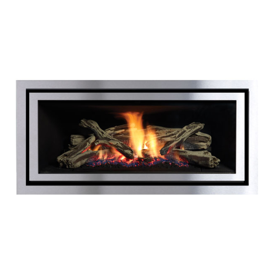
Greenfire
Gas Fireplace
www.regency-fire.com.au
WARNING:
If the information in these instructions are not followed exactly,
a fire or explosion may result causing property damage,
personal injury or loss of life.
FOR YOUR SAFETY
Do not store or use petrol or other flammable vapors and
liquids in the vicinity of this or any other appliance.
Installation and service must be performed by a qualified
installer, service agency or the gas supplier.
919-501d
GF900L
®
Installer: Please complete the details on the back cover
and leave this manual with the homeowner.
Homeowner: Please keep these instructions for future reference.
Owners &
Installation Manual
MODELS: GF900L-NG1
GF900L-LP1
GF900L-ULPG1
GF900L Video
LISTINGS AND CODE APPROVALS
These gas appliances have been tested
in accordance with AS4553 / NZS5262 /
NZS5266 and have been certified by the
Australian Gas Association for installation and
operation as described in these Installation
and Operating Instructions.
Must be installed as per AS/NZS5601-2013
Your unit should be serviced annually by
an authorised service person.
FOR YOUR SAFETY
What to do if you smell gas:
Do not try to light any appliance.
Do not touch any electrical switch.
Do not use any phone in your
building.
Immediately call your gas supplier
from a neighbour's phone. Follow
the gas supplier's instructions.
If you cannot reach your gas
supplier, call the fire department.
19 December 2016
Advertisement
Table of Contents

Related Manuals for Regency Greenfire GF900L Series


Summary of Contents for Regency Greenfire GF900L Series
- Page 1 Operating Instructions. Must be installed as per AS/NZS5601-2013 Your unit should be serviced annually by an authorised service person. www.regency-fire.com.au FOR YOUR SAFETY WARNING: What to do if you smell gas: If the information in these instructions are not followed exactly, Do not try to light any appliance.
-
Page 2: Pairing The Remote Handset And Control Box Id Code
The control box will only learn the Remote ID codes during the first 30 seconds after power is applied and will ignore this special command from the Remote after the first 30 seconds Note: The pairing up process can be carried out by anyone. Note: In addition; please also go to: www.regency-fire.com.au to see the pairing up video. Regency GF900L-1 Gas Fireplace... -
Page 3: Table Of Contents
Electronic components parts list ........50 102mm x 175mm Flueing ..........26 Unit Installation with Horizontal Termination ....27 Main Assembly ............51 Unit installation with Vertical Termination .....28 Accessories ..............53 102mm x 175mm Flueing ..........28 Warranty ..............54 High Elevation ..............29 Regency GF900L-1 Gas Fireplace... -
Page 4: Copy Of Data Badge
DO NOT DO NOT MODIFY THIS APPLIANCE. 908-602a June 25/12 - Added AGA Approval Dec. 23/13: Updated E. Aus address Sept. 23/15: Changed to MJ/hr + added NZ address Feb. 16/16: Rev C - added a -1 Regency GF900L-1 Gas Fireplace... -
Page 5: Unit Dimensions
DIMENSIONS UNIT DIMENSIONS (76mm) (259mm) (500mm) (560mm) (14mm) (1091mm) (522mm) (995mm) (1082mm) (889mm) (795mm) (536mm) (332mm) (725mm) (160mm) (113mm) (1192mm) (989mm) Verona Surround Faceplate Dimensions Regency GF900L-1 Gas Fireplace... -
Page 6: Important Message
9) Wear gloves and safety glasses for protection while doing required maintenance. 10) Be aware of electrical wiring locations in walls and ceilings when cutting holes for termination. Regency GF900L-1 Gas Fireplace... -
Page 7: Installation Checklist
Before leaving this unit with the customer, the installer must ensure that the appliance is firing correctly and operation fully explained to customer. Diagram 1 Flat on Wall Flat on Wall Corner Recessed into Wall/Alcove Corner Regency GF900L-1 Gas Fireplace... -
Page 8: Clearances
See clearance requirements for both mantle (page 9) and or enclosing the NOTE: The unit can be installed onto a combustible base. top of the appliance (Page 11 D dimensions). Installed Close Installed close to Floor to ceiling. Alcove Regency GF900L-1 Gas Fireplace... -
Page 9: Mantel Clearances
(502mm) (667mm) Nailing Flange (254mm) (438mm) To Unit Base Top of Fireplace (610mm) Opening MANTEL LEG CLEARANCES Combustible mantel leg clearances as per diagram: 83mm Non-Combustible MANTEL LEG 38mm 181mm Allowable mantel leg projection 254mm 330mm Regency GF900L-1 Gas Fireplace... -
Page 10: Unit Assembly Prior To Installation
2) Easier access to gas connection with panel removed. 3) Install any optional components with access panel removed. 4) Reinstall access panel with 6 screws Note: Access panel is no longer usable once facing material installed. Installation Access Panel Regency GF900L-1 Gas Fireplace... -
Page 11: Framing Dimensions
NOTE: A minimum thickness of 12mm non-combustible facing board compliant with AS1530-1 and AS1530-3 is required. Drywall or other facing Header Note: All framing may Non-Combustible be of wood construction. Facing NOTE: Do not place timber/steel studs below the timber framing studs Timber already in place. Studs Finished Floor Regency GF900L-1 Gas Fireplace... -
Page 12: Optional Framing Kit
6 screws (2 at bottom, 2 at top and 2 on sides) as shown. per side as shown. NOTE: Ensure the flat side of the steel stud is facing the timber framing. Horizontal stud (466-128) Large stud (466-127) Large stud (466-127) Regency GF900L-1 Gas Fireplace 919-628 12.22.15... -
Page 13: Non Combustible Facing Installation
The finishing of the walls or damage to board. The non combustible board must be surrounding Regency is as critical as the installation itself. The tem- a minimum of 12mm thick and comply with AS1530-1 and peratures around linear gas fireplaces are typically higher than would AS1530-3. -
Page 14: Framing & Finishing
The faceplate will not be able to be mounted if finished material is beyond 38mm. Ensure front of facing mate- rial is flush with the edge of the flange on the fireplace. Regency GF900L-1 Gas Fireplace... -
Page 15: Combustible Requirements
If raising the unit, then the minimum of 12mm non combustible height measurement (A) on page facing is required. 11 of the framing dimensions must be adhered to. For example., Unit raised 300mm then A+ 300mm = 1389mm. Non-combustible Combustible Material Regency GF900L-1 Gas Fireplace 83mm... -
Page 16: Exterior Flue Termination Locations
EXTERIOR FLUE TERMINATION LOCATIONS FIGURE 6.2 (in part): LOCATION OF FLUE TERMINALS OF BALANCED FLUE AS/NZ 5601-2013, ROOM-SEALED, FAN ASSISTED OR OUTDOOR APPLIANCE Regency GF900L-1 Gas Fireplace... -
Page 17: Clearances
4 For appliance not addressed above acceptance should be otained from the Technical Regulator. 5 Minimum clearance d and e also apply to any combustion air intake openings of appliances. Regency GF900L-1 Gas Fireplace... -
Page 18: Flue Restrictor Position
4. Adjust the flue restrictor plate to the required flue restrictor position as per the diagrams shown below. 5. Once the flue restrictor plate is in the required position, secure with screws. Set 0 - 75mm Open Regency GF900L-1 Gas Fireplace... -
Page 19: Flueing Introduction
A flue guard should be used whenever the termination is lower than the specified minimum or as per local codes. • Flex system can only be used up to 3m in total length- otherwise rigid venting must be used. Regency GF900L-1 Gas Fireplace... -
Page 20: Flueing Arrangements
S.S. screws #8 x 1-1/2” drill point Notes: 1) Liner sections should be continuous without any joints or seams. 2) Only Flex pipe purchased from Regency may be ® used for Flex installations 3) Horizontal flue must be supported every 0.9m. -
Page 21: Horizontal Terminations
When using Rigid Flue other than Simpson Dura-Vent, 3 screws must be used to secure rigid pipe to adaptor. The FPI AstroCap and Regency vertical cowls are certified for installations using FPI venting systems as well as Simpson Dura-Vent ® Direct Vent. AstroCap is a proprietary trademark of FPI Fireplace Products International Ltd. -
Page 22: Horizontal Terminations
• Flex system can only be used up to 3m - otherwise rigid flueing must be used. Straight Out Horizontal Venting Diagram 1 center of hole Please note the minimum centerline for basic install shown above. Regency GF900L-1 Gas Fireplace... -
Page 23: Vertical Terminations
Simpson Dura-Vent, 3 screws must be used to secure rigid pipe to adaptor. The FPI AstroCap and Regency vertical Cowl are certified for installations using FPI flueing systems as well as Simpson Dura-Vent ® Direct Vent, is a proprietary trademark of FPI Fireplace Products International Ltd. Dura-Vent® and Direct Vent are registered and/or proprietary trademarks of Simpson Dura-Vent Co. -
Page 24: Flueing Arrangement For Vertical Terminations
Set 0 or Set 3 if required. • Note: For ULPG Flue Restrictor - Set to "0" - 75mm open. Res trictor Set #3 18mm open Regency GF900L-1 Gas Fireplace... -
Page 25: Direct Flue Zero Clearance Top Exit Vertical Flue Kit Installation Instructions Gf900
Note – It is the installers responsibility to ensure the installation complies with AS/NZS 5601-2013 and all local and building codes. NOTE: USE A MINIMUM OF 3 SCREWS EQUIDISTANT TO SECURE EVERY Mill-Pac SEALANT INNER FLUE PIPE JOINT AS WELL INNER FLUE AS MILL-PAC SEALANT Screws Regency GF900L-1 Gas Fireplace... -
Page 26: Unit Installation With Horizontal Termination
4) Level the fireplace and fasten it to the framing using nails or screws through the top and side Diagram 2 nailing strips. Diagram 7 "THIS UNIT MUST ALWAYS NOTE: TERMINATE / FLUE "NOT INTENDED FOR DIRECTLY TO THE OUTDOORS." FIREPLACE INSERT". Regency GF900L-1 Gas Fireplace... -
Page 27: Unit Installation With Horizontal Termination
Wall Thimble 2 pieces and bottom. Fasten the other thimble half to the 254mm inside wall. The thimble halves slip inside each (Outer Diameter) other and can be adjusted for 51mmx102mm or 51mmx152mm. Regency GF900L-1 Gas Fireplace... -
Page 28: Unit Installation With Vertical Termination
6) Ensure vent is vertical and secure the base of the flashing to the roof with roofing rails, slide storm collar over the pipe section and seal with Diagram 2 a mastic. Regency GF900L-1 Gas Fireplace... -
Page 29: High Elevation
Screw in the nut (B) to increase the ease of servicing this appliance. These instructions must be left outlet pressure and screw it out to decrease it. Use a 10 mm wrench. with the appliance. Regency GF900L-1 Gas Fireplace... -
Page 30: Wiring Diagram
MANUAL ON/OFF SWITCH Caution: Ensure that the wires do not touch any hot surfaces and are away from sharp edges. CAUTION: Label all wires prior to disconnection when servicing controls. Wiring errors can cause improper and dangerous operation. Regency GF900L-1 Gas Fireplace... -
Page 31: Conversion From Ng To Lp/Ulpg
3. Remove burner side panels by lifting out as shown in Diagram 1. 6. Remove glass crystals and stones, if installed. 7. Remove 3 screws in locations shown below to remove burner tray. Diagram 1 - Burner Side Panels Diagram 4 - Burner Tray Screw Locations 12/06/16 919-131a Regency GF900L-1 Gas Fireplace... - Page 32 19. Adjust the air shutter opening (See page 33 for Aeration Adjust- ment). For GF900C reverse steps 8-6 and 1. For GF900L reverser steps 5-1. 20. Turn on gas supply and plug in power cord. Regency GF900L-1 Gas Fireplace 919-131a 12/06/16...
-
Page 33: I.t. Valve Description
Minimum Air Shutter Opening: 9.5mm Installer Notice: 13mm These instructions must be left ULPG Full Open with the appliance. Note: Any damage due to carboning resulting from improperly setting the aeration controls is NOT covered under warranty. 12/06/16 919-131a Regency GF900L-1 Gas Fireplace... -
Page 34: Optional Fan Ducting Kit Installation
fl oor NOTE: The fan kit (946-591) does not contain any ducting. The optional extension duct kit (7 in the noted table) is 4.5 metres in length and its part number is 946-596. 919-637 02.16.16 Regency GF900L-1 Gas Fireplace... -
Page 35: Optional Fan Kit Installation
5. Wire up the the fan, wall switch and power supply per local codes. See wiring diagram as reference. *Electrician to supply wiring. 2nd knockout 6. Screw fan junction box to the fan housing. 919-637 02.16.16 Regency GF900L-1 Gas Fireplace... -
Page 36: Fan Duct Extension Kit Installation
Black: High Speed Heat Wave White Fan Assembly Alternate Switches: May use the following. Check with local authorities and electrician. Green CLIPSAL 203 2E45 OUD - Dimmer CLIPSAL 2031 VF3CSF - 3 Speed 919-637 02.16.16 Regency GF900L-1 Gas Fireplace... -
Page 37: Log Set Installation
1. Line up locators on Log 1 with corresponding locators on Log Tray as shown in Diagram 2. Diagram 2 Diagram 4 2. Line up locators on Log 2 with corresponding locators on Ceramic Log Burner as shown in Diagram 3. Diagram 5 Diagram 3 Regency GF900L-1 Gas Fireplace 03/19/12 919-135... - Page 38 6. Log 8 in fi nal position shown in Diagram 11. Diagram 7 Place supplied embers over burner screw holes in locations shown below. 6. Log 5 fi nal position shown in Diagram 8. Diagram 8 Diagram 11 - Log 8 and ember locations Regency GF900L-1 Gas Fireplace 919-135 03/19/12...
-
Page 39: Front Trim Removal / Installation
1. Remove front trim piece - see instructions above. 2. Remove two (2) screws in locations shown below to release panel clips. Panel Clip 3. Remove panels by sliding out. Panel Clip Screw Locations 4. Reverse steps to reinstall. Regency GF900L-1 Gas Fireplace... -
Page 40: Faceplate And Deflector Installation
4. Remove any finger prints/ marks prior to operating the unit. WARNING: Turn off the unit by way of the wall switch or remote. Allow unit to cool at least 10 min. - prior to Diagram 3 removing the faceplate. Regency GF900L-1 Gas Fireplace 11.17.15 919-616... -
Page 41: Screen & Inner Door Frame Installation
Diagram 1 2. Bend Tab on Screen Mesh to 90º as shown in Diagram 2. Secure to Diagram 3 Inner Door Frame with one (1) screw as shown in Diagram 2a. Diagram 2 Diagram 2a Regency GF900L-1 Gas Fireplace 11/13/15 919-220... -
Page 42: Optional Finishing Trim Installation
Press trim inward firmly to seat onto the unit. Note: magnets will keep the trim in place. tooltip 919-220 11/13/15 Finishing Trim Installed 2. Pull trim outward–away from the unit to remove. Regency GF900L-1 Gas Fireplace 11.05.15 919-615 tooltip... -
Page 43: Operating Instructions
1) Plug the power cord into a power outlet. rear of the unit to adjust to the desired speed. Use the Regency Remote Control Kit approved for this unit. Use of other systems may void your 2. There is a black, manual, ON/OFF button Pressing and releasing the plus (+) FAN button warranty. -
Page 44: Copy Of Lighting Plate Instructions
Blower: area for gas. Be sure to smell next to the floor because Regency gas appliances use high tech blowers 2) Press and hold down the reset button for at some gas is heavier than air and will settle on the floor. -
Page 45: Fan Service
Diagram 2 - Burner Screw Locations 5. Remove rear log tray by removing 3 screws as shown in Diagram 3 below. Diagram 6 - Fan Screws 9. Reverse steps to reinstall fan. Diagram 3 - Log Tray screws Regency GF900L-1 Gas Fireplace... -
Page 46: Maintenance Instructions
Replacement of the glass panels serviced check that the vent-air system should be done by a licensed or has been properly resealed & reinstalled in accordance with the manufacturer's qualified service person. instructions. 8) Verify operation after servicing. Regency GF900L-1 Gas Fireplace... -
Page 47: Troubleshooting
Providing the pressure switch has continuity and convection fan is creating pressure,the electrode should spark and the gas valve open within 5 seconds of the completion of the purge cycle. Regency GF900L-1 Gas Fireplace... -
Page 48: Glass Door Installation
6. Pull the bottom of the door towards you until the door is angled away from the firebox by about 30°. Lift the door up and over the upper door hooks. 7. To install the glass door - reverse steps. Regency GF900L-1 Gas Fireplace... -
Page 49: Valve Tray Replacement
Diagram 5 - Valve Tray Removal Diagram 2 - Burner Screw Locations Replace valve tray and reverse steps. 5. Remove rear log tray by removing 3 screws as shown in Diagram 3 below. Diagram 3 - Log Tray screws Regency GF900L-1 Gas Fireplace... -
Page 50: Electronic Components Parts List
911-121 Ignition Module (2) 910-514 Jumper Wire 910-935 Manual Control Switch **Note: The Control Box Cable wires for the FG38 come separately: 910-502, 910-505, 910-506, 910-507, 910-509 Regency GF900L-1 Gas Fireplace... -
Page 51: Main Assembly
Right Panel Bracket 911-113 Switch On/Off w/Cat 5 cable 396-038 Bottom Door Latch Retainer 910-155/P Blower Motor 466-930 Log Set 911-161 Black Reset Button 466-063 Valve mounting gasket 466-064 Access plate gasket Not Shown 919-501 Manual Regency GF900L-1 Gas Fireplace... - Page 52 PARTS LIST MAIN ASSEMBLY Regency GF900L-1 Gas Fireplace...
-
Page 53: Accessories
Inner door frame - Stainless w/ Screen 33 467-544 Door Frame Overlay - Black 34 467-938 Fascia and Door Frame Black w/Screen 467-936 Fascia and Door Frame Stainless Steel w/Screen 467-951 Fascia Black Glass (not shown) Regency GF900L-1 Gas Fireplace... -
Page 54: Warranty
FPI Fireplace Products International Ltd. (“the manufacturer”) through its wholly owned subsidiary, Fireplace Products Australia Pty Ltd (for Australia and New Zealand customers) and sold under the Regency® brand of fireplace products (collectively referred to herein as “FPI”), extends this Limited Lifetime Warranty to the original purchaser of this appliance provided the product remains in the original place of installation. - Page 55 Limited Lifetime Warranty. Revision Date: December 2016 Regency Gas Products Warranty Regency GF900L-1 Gas Fireplace...
- Page 56 FPI may void this warranty. INCORRECT INSTALLATION OR GAS PRESSURE SETTINGS ARE NOT COVERED BY WARRANTY. A SERVICE OR CALLOUT FEE WILL BE CHARGED IN THESE CIRCUMSTANCES. Revision Date: December 2016 Regency Gas Products Warranty Regency GF900L-1 Gas Fireplace...
- Page 57 (including negligence), statute or otherwise. (b) Loss means any expense, cost or damage of any kind and includes Consequential Loss and a fine or penalty imposed by a statutory or other authority. Revision Date: December 2016 Regency Gas Products Warranty Regency GF900L-1 Gas Fireplace...
- Page 58 Product Registration and Customer Support: Thank you for choosing a Regency Fireplace. Regency strives to be a world leader in the design, manufacture, and marketing of hearth products. To provide the best support for your product, we request that you complete a product registration form at http://www.regency-fire.com.au/Customer-Care/Warranty-Registration.aspx...
- Page 59 Product Registration and Customer Support: Thank you for choosing a Regency Fireplace. Regency strives to be a world leader in the design, manufacture, and marketing of hearth products. To provide the best support for your product, we request that you complete a product registration form found on our Web Site under Customer Care within ninety (90) days of purchase.
- Page 60 Regency GF900L-1 Gas Fireplace...
- Page 61 NOTES notes Regency GF900L-1 Gas Fireplace...
- Page 62 NOTES Regency GF900L-1 Gas Fireplace...
- Page 63 Regency GF900L-1 Gas Fireplace...
- Page 64 Dealer Name & Address: ______________________________________________ ___________________________________________________________________ Installer: ___________________________________________________________ Phone #: ___________________________________________________________ Date Installed: ______________________________________________________ Serial No.: __________________________________________________________ Regency and Greenfire are registered trademarks of FPI Fireplace Products International Ltd. GF900L Video © Copyright 2016, FPI Fireplace Products International Ltd. All rights reserved.
Need help?
Do you have a question about the Greenfire GF900L Series and is the answer not in the manual?
Questions and answers