Table of Contents
Advertisement
Quick Links
EN
For proper operation, please read and keep this manual carefully.
Designed by Cooper&Hunter International Corporation, Oregon, USA
OWNER'S MANUAL
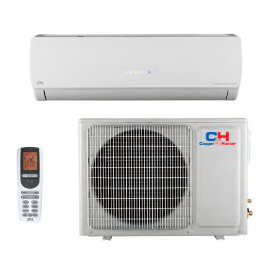
Heat Pump Air To Air
Split Air Conditioner
ICY II
M ODELS :
www.cooperandhunter.com
Series
CH-S09FTXTB2S-W
CH-S12FTXTB2S-W
CH-S18FTXTB2S-W
CH-S24FTXTB2S-W
Advertisement
Table of Contents

Related Manuals for Cooper & Hunter CH-S12FTXTB2S-W


Summary of Contents for Cooper & Hunter CH-S12FTXTB2S-W
- Page 1 OWNER’S MANUAL Heat Pump Air To Air Split Air Conditioner ICY II Series M ODELS : CH-S09FTXTB2S-W CH-S12FTXTB2S-W CH-S18FTXTB2S-W CH-S24FTXTB2S-W For proper operation, please read and keep this manual carefully. Designed by Cooper&Hunter International Corporation, Oregon, USA www.cooperandhunter.com...
-
Page 2: Table Of Contents
Content Operation Notices Precautions......................1 Parts Name......................6 Screen Operation Guide Buttons on remote controller..................7 Introduction for icons on display screen..............7 Introduction for buttons on remote controller............8 Function introduction for combination buttons............. 11 Operation guide....................Replacement of batteries in remote controller............Emergency operation . - Page 3 Explanation of Symbols Indicates a hazardous situation that, if not avoided, will DANGER result in death or serious injury. Indicates a hazardous situation that, if not avoided, could WARNING result in death or serious injury. Indicates a hazardous situation that, if not avoided, may CAUTION result in minor or moderate injury.
-
Page 4: Precautions
Precautions WARNING Operation and Maintenance This appliance can be used by children aged from 8 years and above and persons with reduced physical, sensory or mental capabilities or lack of experience and knowledge if they have been given supervision or instruction concerning use of the appliance in a safe way and understand the hazards involved. - Page 5 Precautions WARNING Maintenance must be performed by qualified professionals. Otherwise, it may cause personal injury or damage. Do not repair air conditioner by yourself. It may cause electric shock or damage. Please contact dealer when you need to repair air conditioner. Do not extend fingers or objects into air inlet or air outlet.
- Page 6 Precautions WARNING Attachment Installation must be performed by qualified professionals. Otherwise, it may cause personal injury or damage. Must follow the electric safety regulations when installing the unit. According to the local safety regulations, use qualified power supply circuit and circuit break. Do install the circuit break.
- Page 7 Precautions WARNING Do not put through the power before finishing installation. If the supply cord is damaged, it must be replaced by the manufacturer, its service agent or similarly qualified persons in order to avoid a hazard. The temperature of refrigerant circuit will be high, please keep the interconnection cable away from the copper tube.
- Page 8 Precautions WARNING For the air conditioner with plug, the plug should be reachable after finishing installation. For the air conditioner without plug, an circuit break must be installed in the line. If you need to relocate the air conditioner to another place, only the qualified person can perform the work.
-
Page 9: Parts Name
Parts Name Indoor Unit air inlet aux.button horizontal louver air outlet cooling power receiver indicator indicator window display heating temp. drying indicator indicator indicator (Display content or position may be different from above remote control graphics, please refer to actual products) Outdoor Unit air inlet handle... -
Page 10: Buttons On Remote Controller
Buttons on remote controller Notice:This is a general remote ON/OFF controller. Some models have this Press it to start or stop operation. function while some do not. Please refer to the actual models. : Press it to decrease temperature setting. : Press it to increase temperature setting. -
Page 11: Introduction For Buttons On Remote Controller
Introduction for buttons on remote controller ON/OFF : Press this button to turn on the unit .Press this button again to turn off the unit. Press this button to decrease set temperature. Holding it down above 2 seconds rapidly decreases set temperature. In AUTO mode, set temperature is not adjustable. Press this button to increase set temperature.Holding it down above 2 seconds rapidly increases set temperature. - Page 12 Introduction for buttons on remote controller ress this button to achieve the on and off of healthy and scavenging functions in operation status.Press this button for the first time to start scavenging function; LCD displays“ ”. Press the button for the second time to start healthy and scavenging functions simultaneously;...
- Page 13 Introduction for buttons on remote controller TEMP: Press this button, could select displaying the indoor setting temperature or indoor ambient temperature.When the indoor unit firstly power on it will display the setting temperature, if the temperature's displaying status is changed from other status to" ",displays the ambient temperature, 3s later or within 3s, it receives other remote control signal that will return to display the setting temperature.
-
Page 14: Function Introduction For Combination Buttons
Function introduction for combination buttons Energy-saving function Under cooling mode, press "TEMP" and "CLOCK" buttons simultaneously to start up or turn off energy-saving function. When energy-saving function is started up, "SE" will be shown on remote controller, and air conditioner will adjust the set temperature automatically according to ex-factory setting to reach to the best energy-saving effect. - Page 15 Function introduction for combination buttons Temperature display switchover function Under OFF status, press " " and "MODE" buttons simultaneously to switch temp- erature display between ℃ and ℉ . WIFI Function Press "MODE" and "TURBO" button simultaneously to turn on or turn off WIFI function.
-
Page 16: Operation Guide
Operation guide After putting through the power, press "ON/OFF" button on remote controller to turn on the air conditioner. Press "MODE" button to select your required mode: AUTO, COOL, DRY, FAN, HEAT. Press "▲" or " " button to set your required temperature. (Temperature can’t be adjusted under auto mode). -
Page 17: Emergency Operation
Emergency operation If remote controller is lost or damaged, please use auxiliary button to turn on or turn off the air conditioner. The operation in details are as below: air conditioner. When the air conditioner is turned on, it will operate under auto mode. - Page 18 Clean and Maintenance Open panel ● Use dust catcher or water to Pull out the panel to a certain the water (below 45℃ ) to clean it, and then put it in a shady and cool place to dry. panel cover tightly. WARNING operation environment, clean frequency can be increased.
- Page 19 Clean and Maintenance NOTICE: Checking before use-season 1. Check whether air inlets and air outlets are blocked. 2. Check whether air switch, plug and socket are in good condition. 4. Check whether mounting bracket for outdoor unit is damaged or corroded. If yes, please contact dealer.
-
Page 20: Malfunction Analysis
Malfunction analysis General phenomenon analysis Please check below items before asking for maintenance. If the malfunction still Phenomenon Check items Solution ● Whether it's interfered severely ● Pull out the plug. Reinsert (such as static electricity, stable the plug after about 3min, and voltage)? then turn on the unit again. - Page 21 Malfunction analysis Phenomenon Check items Solution ● Power failure? ● Wait until power recovery. ● Is plug loose? ● Reinsert the plug. ● Air switch trips off or fuse is ● Ask professional to replace burnt out? air switch or fuse. Air condit- ●...
- Page 22 Malfunction analysis Phenomenon Check items Solution ● Whether there’s odour source, ● Eliminate the odour source. Odours are such as furniture and cigarette, emitted etc. ● Whether there’s interference, ● Disconnect power, put back Air conditioner such as thunder, wireless power, and then turn on the operates devices, etc.
- Page 23 Malfunction analysis Error Code ● When air conditioner status is abnormal, temperature indicator on indoor unit will ation of error code. Above indicator diagram is only for reference. Please refer to Indoor display actual product for the actual indicator and position. Error code Error code Troubleshooting...
-
Page 24: Installation Dimension Diagram
Installation dimension diagram Space to the wall At least 15cm Drainage pipe... -
Page 25: Tools For Installation
Tools for installation 1 Level meter 2 Screw driver 3 Impact drill 4 Drill head 5 Pipe expander 6 Torque wrench 7 Open-end wrench 8 Pipe cutter 9 Leakage detector 10 Vacuum pump 11 Pressure meter 12 Universal meter 13 Inner hexagon spanner 14 Measuring tape Note: ●... -
Page 26: Requirements For Electric Connection
Requirements for electric connection Safety precaution 1. Must follow the electric safety regulations when installing the unit. air switch. 3. Make sure the power supply matches with the requirement of air conditioner. Unstable power supply or incorrect wiring or malfunction. Please install proper power supply cables before using the air conditioner. -
Page 27: Installation Of Indoor Unit
Installation of indoor unit Step one: choosing installation location rm it with the client. Step two: install wall-mounting frame 1. Hang the wall-mounting frame on the wall; adjust it in horizontal position with the plastic expansion particles in the holes. 3. - Page 28 Installation of indoor unit Indoor outdoor Note: ● Pay attention to dust prevention and take relevant safety measures when opening the hole. Φ55/ ● The plastic expansion particles are 5-10 Φ70 not provided and should be bought locally. Step four: outlet pipe 1.
- Page 29 Installation of indoor unit Hex nut diameter Tightening torque (N . m) open-end Φ 6 15~20 wrench Φ 9.52 30~40 union nut Φ 12 45~55 Φ 16 60~65 pipe torque wrench Φ 19 70~75 indoor pipe 4. Wrap the indoor pipe and joint of con- nection pipe with insulating pipe, and then wrap it with tape.
- Page 30 Installation of indoor unit 2. Make the power connection wire go cable-cross through the cable-cross hole at the back hole of indoor unit and then pull it out from the front side. power connection wire 3. Remove the wire clip; connect the power connection wire to the wiring terminal according to the color;...
- Page 31 Installation of indoor unit Step eight: bind up pipe 1. Bind up the connection pipe, power drain hose connection pipe band cord and drain hose with the band. indoor unit indoor and outdoor power cord pipe indoor power cord liquid pipe 3.
-
Page 32: Installation Of Outdoor Unit
Installation of outdoor unit (select it according to the actual installation situation) 1. Select installation location according to the house structure. 2. Fix the support of outdoor unit on the selected location with expansion screws. Note: installing the outdoor unit. ●... - Page 33 Installation of outdoor unit Step four: connect indoor and outdoor pipes 1. Remove the screw on the right han- 3. Pretightening the union nut with dle of outdoor unit and then remove hand. the handle. pipe joint screw handle yellow- green union nut 2.
- Page 34 Installation of outdoor unit 2. Fix the power connection wire and signal control wire with wire clip (only for cooling and heating unit). Note: ● Never cut the power connection wire to prolong or shorten the distance. Step six: neaten the pipes 1.
-
Page 35: Vacuum Pumping
Vacuum pumping Use vacuum pump 1. Remove the valve caps on the liquid valve and gas liquid valve piezometer valve and the nut of refri- gas valve gerant charging vent. refrigerant charging 2. Connect the charging hose valve cap vent of piezometer to the refri- gerant charging vent of gas nut of refrigerant... -
Page 36: Check After Installation
Check after installation Items to be checked Possible malfunction The unit may drop, shake or emit noise. Have you done the refrigerant leakage test? (heating) capacity. It may cause condensation and water dripping. It may cause condensation and water Is water drained well? dripping. -
Page 37: Configuration Of Connection Pipe
Configuration of connection pipe 1. Standard length of connection pipe ● 5m, 7.5m, 8m. 2.Min. length of connection pipe is 3m. 3.Max. length of connection pipe and max. high difference. Max length Max length Cooling Max height Cooling Max height of connec- of connec- capacity... - Page 38 Configuration of connection pipe Additional refrigerant charging amount for R22, R407C, R410A and R134a Diameter of connection pipe Outdoor unit throttle Liquid pipe(mm) Gas pipe(mm) Cooling only(g/m) Cooling and heating(g/m) Φ6 Φ9.52 or Φ12 Φ6 or Φ9.52 Φ16 or Φ19 Φ12 Φ19 or Φ22.2 Φ16...
-
Page 39: Pipe Expanding Method
Pipe expanding method Note: Improper pipe expanding is the main cause of refrigerant leakage. Please expand the pipe according to the following steps: A: Cut the pipe E: Expand the port ● Expand the port with expander. the distance of indoor unit and hard outdoor unit. - Page 40 Designed by Cooper&Hunter International Corporation, Oregon, USA www.cooperandhunter.com E-mail: info@cooperandhunter.com * Co o o o o per & & w w w o o rk k im m m pro o o v v e th h inf f f o ch h 66160000324...
Need help?
Do you have a question about the CH-S12FTXTB2S-W and is the answer not in the manual?
Questions and answers